
Two-way twistable staggered-comb teeth electrostatic driving variable optical attenuator and manufacture method thereof

An electrostatic drive, optical attenuator technology, applied in the direction of electric solid devices, instruments, circuits, etc., can solve the problems of asymmetric structure, complex process, difficult linear control and so on

Inactive Publication Date: 2015-01-28
SOUTHEAST UNIV
View PDF4 Cites 0 Cited by
  • Summary
  • Abstract
  • Description
  • Claims
  • Application Information

AI Technical Summary

Problems solved by technology

There are flat plate type and comb type drive structures. The flat type is difficult to achieve linear control, and the comb teeth need to overlap up and down. The processing of the upper and lower comb teeth involves alignment and isolation issues, so the process is relatively complicated. If the comb teeth are concentrated on one side, May cause structural asymmetry, easy to lose balance

Method used


Image

  • Two-way twistable staggered-comb teeth electrostatic driving variable optical attenuator and manufacture method thereof
  • Two-way twistable staggered-comb teeth electrostatic driving variable optical attenuator and manufacture method thereof
  • Two-way twistable staggered-comb teeth electrostatic driving variable optical attenuator and manufacture method thereof

Examples


Embodiment Construction

[0027] The technical solution of the present invention will be described in further detail below in conjunction with the accompanying drawings.

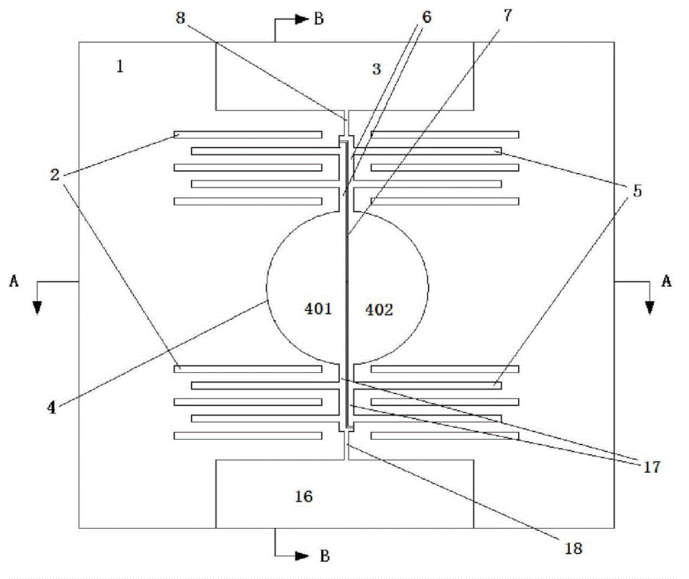
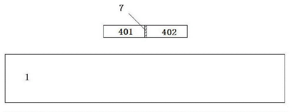
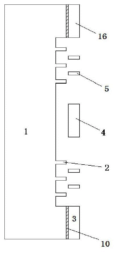
[0028] Such as Figure 1 to Figure 3As shown, the bidirectionally twistable interlaced comb tooth electrostatically driven variable optical attenuator of the present invention includes a substrate 1 with a cavity on the upper part, four fixed comb units 2 fixedly connected in the cavity of the substrate 1, Micromirror 4, four movable comb units 5, first pole 6, insulating medium layer 7, first torsion bar 8, second pole 17, second torsion bar 18, and the first torsion bar above the substrate 1 The active electrode area 3 and the second active electrode area 16 . The first active electrode region 3 and the second active electrode region 16 are fixedly connected to the substrate 1 with the oxide insulating layer 10 respectively. The oxide insulating layer 10 isolates the first active electrode region 3 and the second active electrode...


PUM


Abstract

The invention discloses a two-way twistable staggered-comb teeth electrostatic driving variable optical attenuator which comprises a substrate, fixed comb teeth units, a micromirror, movable comb teeth units, two support rods, insulating medium layers, two twisting rods and two movable electrode regions, wherein an oxidation insulating layer is fixedly connected between each of the two movable electrode regions and the substrate, and the insulating medium layers are respectively embedded to the middle parts of the two support rods, the two twisting rods and the micromirror; one ends of the two support rods are fixedly connected onto the micromirror, and the other ends of the two support rods are fixedly connected onto the movable electrode regions by the twisting rods; and two movable comb teeth units which are symmetrically arranged with each other along the support rods are respectively and fixedly connected onto the two support rods, and movable comb teeth in each movable comb teeth unit and fixed comb teeth in each fixed comb teeth unit are distributed with one another in a staggered way. According to the variable optical attenuator, the two-way twisting can be realized, and the twisting position of the micromirror can be accurately controlled. Meanwhile, the invention further discloses a preparation method of the variable optical attenuator, which is high in reliability and high in machining precision.

Description

technical field [0001] The invention relates to a variable optical attenuator and a preparation method thereof, in particular to an electrostatically driven variable optical attenuator capable of bidirectional twisting with interlaced comb teeth and a preparation method thereof. Background technique [0002] Variable optical attenuator (VOA for short) is an important fiber optic passive device in optical network. It is a key component of optical amplifier and plays a key role in power balance in optical fiber communication system. Micro-Electro-Mechanical Systems (MEMS for short) variable optical attenuator has reliable performance, compact structure, low cost, easy mass production, and has broad development prospects. The current MEMS variable optical attenuator mainly has a micromirror structure, and the up and down deflection of the micromirror is realized through electrostatic drive. There are flat plate type and comb type drive structures. The flat type is difficult to...

Claims


Application Information

Patent Timeline
Patent Type & Authority Patents(China)
IPC IPC(8): G02B26/08B81B7/00
Inventor 秦明
Owner SOUTHEAST UNIV
Learn More