
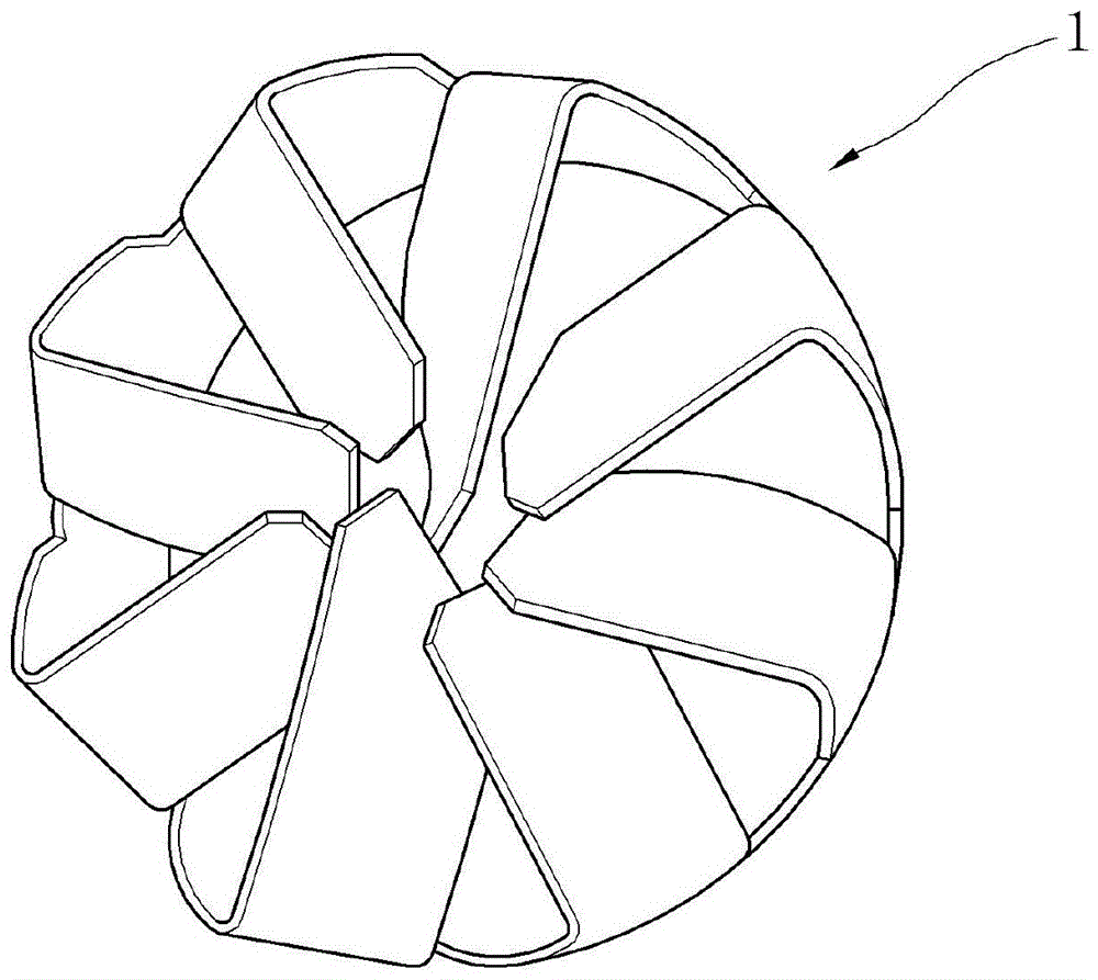
Mixing equipment for exhaust gases in automobiles

A technology for mixing equipment and exhaust gas, which is applied in the direction of mixers, mechanical equipment, fluid mixers, etc., and can solve the problems of deterioration of mixing properties and not causing secondary mixing properties, etc.

Active Publication Date: 2016-12-21
HYUNDAI MOTOR CO LTD +1
View PDF6 Cites 0 Cited by
  • Summary
  • Abstract
  • Description
  • Claims
  • Application Information

AI Technical Summary

Problems solved by technology

[0007] However, according to the related art, the flow of exhaust gas is limited to one direction, so the second mixing property is not caused in the existing diffusion device, thereby deteriorating the mixing property

Method used


Image

  • Mixing equipment for exhaust gases in automobiles
  • Mixing equipment for exhaust gases in automobiles
  • Mixing equipment for exhaust gases in automobiles

Examples


Embodiment Construction

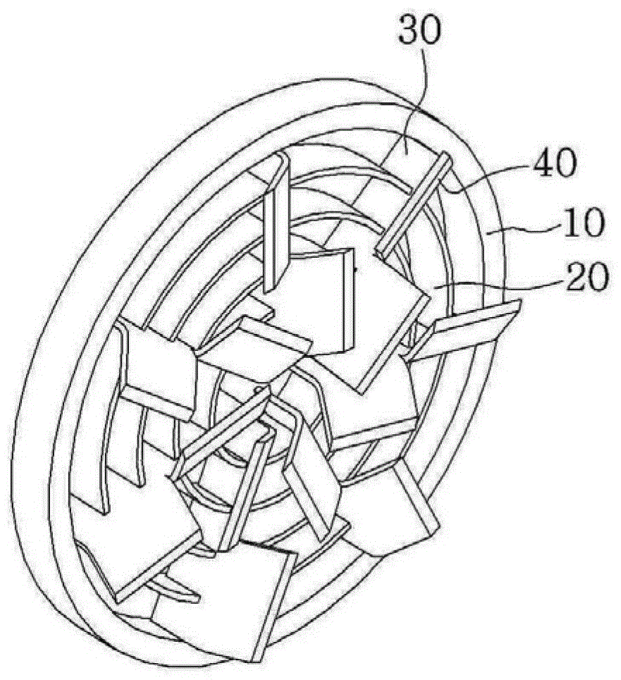
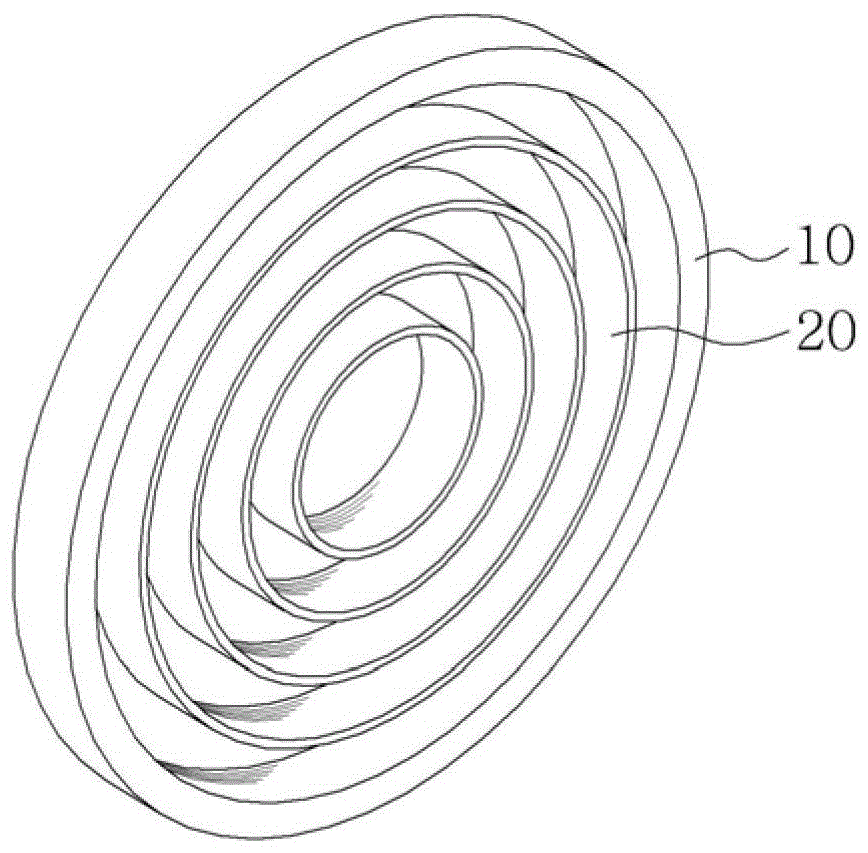
[0028] Hereinafter, a mixing device for exhaust gas according to an exemplary embodiment of the present invention will be described with reference to the accompanying drawings.

[0029] A mixing device for exhaust gas is provided in the exhaust pipe of the engine to cause uniform mixing of the exhaust gas and the reducing agent by uniformly diffusing them, and additionally the double swirl of the exhaust gas passes through said mixing device, thereby increasing the exhaust gas and the reducing agent mixed nature.

[0030] Before describing in detail the mixing device for exhaust gases according to the invention, said mixing device can vary in size so that it can be installed anywhere in the exhaust pipe of the engine, in addition, it can be provided as plug-in type or fixed type . In particular, the fixing device can be arranged in the following positions according to the layout of the exhaust system: where the exhaust flow is concentrated, or where the reducing agent needs t...


PUM


Abstract

The present invention relates to a mixing device for exhaust gas in automobiles, more particularly to a mixing device for exhaust gas capable of increasing the mixing between exhaust gas and reducing agent by making the exhaust gas passing through said mixing device into a double swirl nature. The mixing device for exhaust gas includes: a hollow plate-type flange, a frame member and a diffuser plate, the hollow plate-type flange is arranged on the flow path of exhaust gas; the diameter of the frame member is toward the center of the flange taper; the diffuser plate separates the interior of the flange and diffuses the exhaust gas and reductant injected through the injector.

Description

[0001] Cross References to Related Applications [0002] This application claims the benefit of filed Korean Patent Application No. 10-2011-0122359 under 35 U.S.C. §119(a), which is incorporated herein by reference. technical field [0003] The present invention relates to a mixing device for exhaust gas in automobiles, more particularly to a mixing device for exhaust gas capable of increasing the mixing between exhaust gas and reducing agent by making the exhaust gas passing through said mixing device into a double swirl nature. Background technique [0004] Generally, exhaust gas discharged from the engine through the exhaust manifold is guided to a diesel particulate filter (hereinafter referred to as "DPF"), a selective catalytic reduction device (hereinafter referred to as "SCR device"), or The NOx storage reduction catalyst (hereinafter referred to as "NSR catalyst") is purified and the exhaust gas passes through the muffler while its noise is reduced, and then the ex...

Claims


Application Information

Patent Timeline
Patent Type & Authority Patents(China)
IPC IPC(8): F01N3/28
CPCB01F25/4315B01F25/431974B01F25/4323B01D53/94F01N3/28
Inventor 金昌大
Owner HYUNDAI MOTOR CO LTD
Learn More