
Method of online monitoring for high-voltage switch contact temperature rise

A contact temperature rise, high-voltage switch technology, applied in thermometers, measuring devices, measuring heat and other directions, can solve the problems of high price of optical fiber thermometers, aging of optical fiber insulation, troublesome installation and renovation of optical fiber thermometers, etc.

Inactive Publication Date: 2013-05-22
LIAONING JULONG TENGFEI ELECTRICAL +1
View PDF1 Cites 7 Cited by
  • Summary
  • Abstract
  • Description
  • Claims
  • Application Information

AI Technical Summary

Problems solved by technology

The non-contact temperature measurement method adopts thermal infrared detection technology, which is made according to the certain functional relationship between the relative radiation intensity and temperature of the object. Its advantages are large measurement range and high accuracy, but in practical applications due to There are great limitations due to the limitation of the angle of view and the distance coefficient of the instrument itself. Another disadvantage of the infrared thermometer is that it needs manual inspection, and sometimes it is affected by factors such as weather. It cannot detect the high voltage enclosed in the cabinet. Switch contacts, unable to realize the integrated integration of high-voltage equipment and online temperature detection
There are many contact temperature measurement methods, mainly as follows: (1) color temperature film method, using color film (also known as temperature recording label), which undergoes a series of chemical and physical changes after being heated, from the change of molecular structure, The color of the reflected light changes, and the temperature can be judged according to its color. The disadvantage is that the accuracy is low, the reliability is poor, and quantitative measurement cannot be performed. Moreover, for high-voltage switch contacts, etc., the color is almost invisible when running in a closed cabinet. (2) Optical fiber temperature measurement technology. With the support of the American Electric Power Research Institute (EPRI), Luke Corporation of the United States has developed a fluorescent optical fiber temperature measurement device specially developed and produced for power system applications to monitor the temperature of transformer windings. Brand-new on-line monitoring technology for internal temperature of high-voltage electrical equipment. Optical fiber has good electrical insulation performance and anti-electromagnetic interference ability. At the same time, the probe can be buried in a high-voltage selected part inside the power equipment to directly measure the actual temperature change at that point. However, the fiber optic thermometer is expensive, and the installation and transformation of the fiber optic thermometer is troublesome. After long-term operation, the insulation of the fiber is aging, causing mutual breakdown between the high and low voltage sides. The fiber optic temperature measurement technology has not yet been popularized in China; (3) Others Contact temperature measurement: There have also been a variety of online contact temperature measurement solutions in China. The main method is to install the temperature sensor on the switch contact, and send the temperature signal to the ground through radio frequency technology or light intensity modulation technology, and then the ground computer controls the temperature. The temperature signal is processed. These solutions all have the problem of how to supply power to the temperature sensor without exception. There are usually the following power supply methods (1) Battery method: the biggest disadvantage is that it cannot guarantee normal power supply during the entire high-voltage side non-maintenance period; (2) ) Photocell method: The high-voltage side sensor uses silicon photocells, and the light source is provided by the low-voltage side of the ground, so that the sensor is powered on. The disadvantage is that it is not easy to install and the interphase insulation of the high-voltage side is affected by the large area of ​​the silicon photocell after installation; (3) Power supply on the low-voltage side : The disadvantage is that there is a potential for mutual feed and breakdown between the low-voltage side and the high-voltage side

Method used


Image

  • Method of online monitoring for high-voltage switch contact temperature rise
  • Method of online monitoring for high-voltage switch contact temperature rise
  • Method of online monitoring for high-voltage switch contact temperature rise

Examples


Embodiment Construction

[0020] An online monitoring method for temperature rise of high-voltage switch contacts, characterized in that:

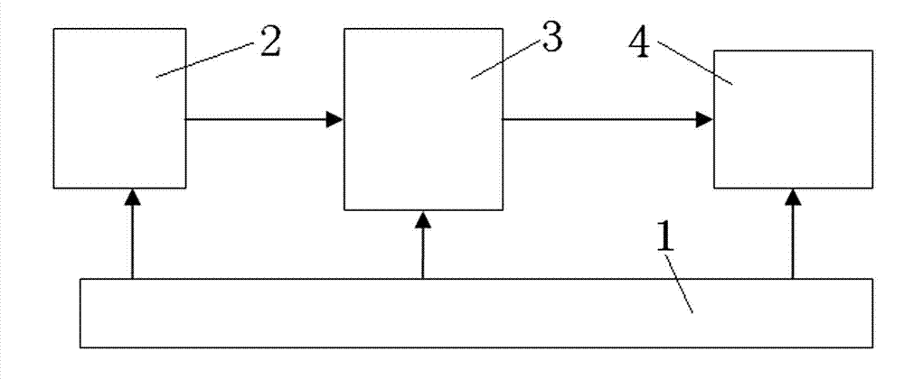
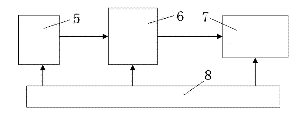
[0021] 1. The online monitoring equipment used is an online monitoring device for the temperature rise of high-voltage switch contacts, including the power supply circuit 1 of the transmitting part, the temperature acquisition circuit 2, the microprocessor of the transmitting part 3, the wireless transmitting circuit 4, the wireless receiving circuit 5, and the receiving part. The microprocessor 6, the display circuit 7 of the receiving part and the power supply circuit 8 of the receiving part.

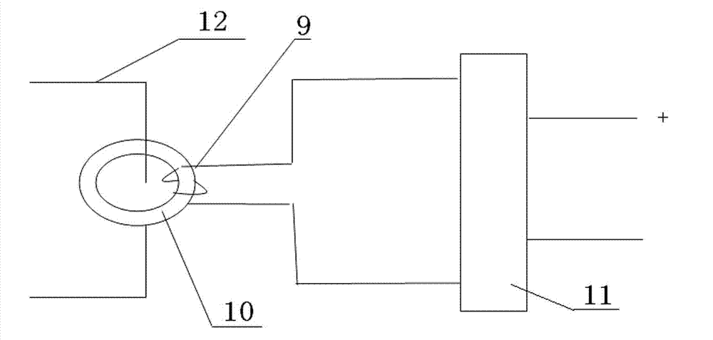
[0022] The power supply circuit 1 of the transmitting part is composed of a current induction coil 9, an annular iron core 10 and a voltage conversion module 11. The current induction coil 9 is wound on the annular iron core 10, and the two leads of the current induction coil 9 correspond to the voltage conversion module 11. The connection terminal is connected, and the vo...


PUM


Abstract

Disclosed is a method of online monitoring for high-voltage switch contact temperature rise. Equipment used by the method includes a transmitting part power circuit, a temperature acquisition circuit, a transmitting part microprocessor, a wireless transmitting circuit, a wireless receiving circuit, a receiving part microprocessor, a display circuit and a receiving part power circuit. The transmitting part power circuit comprises a current induction coil and a circular core, the core is sleeved on a conductor of a switch contact to be measured, and induction current of the current induction coil is used to power the temperature acquisition circuit, the transmitting part microprocessor and the wireless transmitting circuit. Temperature signals acquired by the temperature acquisition circuit are processed and are then transmitted by the wireless transmitting circuit. The wireless receiving circuit receives the signals. After the microprocessor processes the signals, the display circuit displays measured switch contact temperature. When temperature rise exceeds a set upper limit, alarm signals are sent out. Failure of the high-voltage switch contact can be monitored effectively, and safe operation of a power system can be guaranteed effectively.

Description

technical field [0001] The invention relates to a circuit and a method for monitoring the temperature rise of a high-voltage switch contact on-line by using wireless radio frequency technology, and then diagnosing the failure of the high-voltage switch contact to ensure the safe operation of a power system. Background technique [0002] In order to ensure the safe operation of the power system, the diagnosis of thermal faults in the power system is generally valued by people. When the high-voltage bus is overloaded or the contact of the high-voltage switch is not in good contact, the contact resistance will become larger and heat will be generated when the load current flows. , This heating phenomenon causes insulation aging or even breakdown, thereby causing a short circuit, forming a major accident, and causing major economic losses. [0003] In the power supply system using power cables for power transmission and distribution, statistics show that more than 90% of cable f...

Claims


Application Information

Patent Timeline
Patent Type & Authority Applications(China)
IPC IPC(8): G01K7/00G01K7/22G08C17/02
Inventor 李瑞祥唐海峰迟海宁梁倩李楠
Owner LIAONING JULONG TENGFEI ELECTRICAL
Learn More