
Portable strong crossbow

A portable and strong crossbow technology, which is applied to bows/crossbows, weapons without explosives, sports accessories, etc., can solve the problems of limited crossbow range, poor range, strong bow, etc., achieve good guiding effect, improve hit rate, and carry convenient effect

Inactive Publication Date: 2013-05-22
潘佳伟
View PDF7 Cites 9 Cited by
  • Summary
  • Abstract
  • Description
  • Claims
  • Application Information

AI Technical Summary

Problems solved by technology

The crossbows of the prior art still have the following deficiencies. Firstly, due to the limitations of the traditional "bow" structure, they cannot provide a longer crossbow booster slideway, and basically rely on the short-term tension of the bow to push the crossbow. The thrust is limited, that is, the crossbow cannot be pushed. Obtain enough momentum, the shooting range is not good, and the short slideway is also not conducive to the stability of the crossbow in the direction of launch; secondly, the crossbow of the prior art is generally launched by lifting the arm, which is not convenient for aiming, and the hit rate is low; again , relying on the arm to pull the string and buckle it on the crossbow, the operation is laborious, so the bow cannot be made too strong, which also limits the range of the crossbow

Method used


Image

  • Portable strong crossbow
  • Portable strong crossbow
  • Portable strong crossbow

Examples


Embodiment Construction

[0042] The principles and features of the present invention are described below in conjunction with the accompanying drawings, and the examples given are only used to explain the present invention, and are not intended to limit the scope of the present invention.

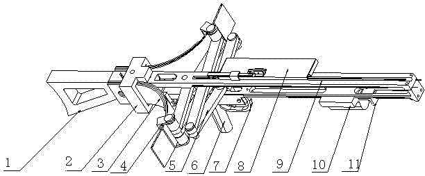
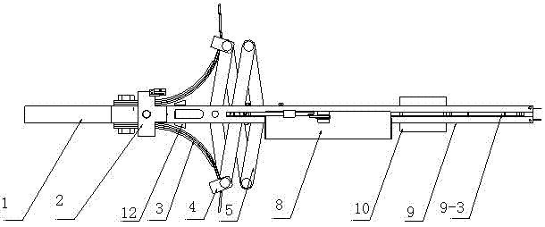
[0043] Such as Figure 1 to Figure 12 As shown, a portable crossbow includes a crossbow support 1, a crossbow frame 9, a handle 6, a trigger mechanism 7 and an ejection mechanism, wherein the crossbow support 1 is fixedly connected to the rear end of the crossbow frame 9, The crossbow frame 9 is provided with a chute 9-3 along the ejection direction, the handle 6 is fixed on the lower part of the crossbow frame 9, and the trigger mechanism 7 is arranged on the crossbow frame at the front part of the handle 6 superior;

[0044] The ejection mechanism includes symmetrically arranged left and right elastic plates 3 and a scissor telescopic mechanism 5;

[0045]The scissor telescopic mechanism 5 includes a scissor ar...


PUM


Abstract

The invention discloses a portable strong crossbow which comprises a crossbow support, a crossbow frame, a gripping handle, a trigger mechanism and an ejection mechanism. The crossbow support is fixedly connected with the rear end of the crossbow frame, a sliding groove is formed in the crossbow frame along the ejection direction, the gripping handle is fixed on the lower portion of the crossbow frame, and the trigger mechanism is arranged on the position, at the front portion, of the crossbow frame. The ejection mechanism comprises a left elasticity plate, a right elasticity plate, and a shear type telescopic mechanism, wherein the left elasticity plate and the right elasticity plate are arranged symmetrically, the rear end of the left elasticity plate and that of the right elasticity plate are fixed on the rear portion of the crossbow frame, the front of the left elasticity plate and that of the right elasticity plate are movably connected with the shear type telescopic mechanism, the shear type telescopic mechanism is connected on the crossbow frame through a rear hinge pin hole and a rear hinge pin, a front hinge pin is arranged in the front hinge pin hole, the shear type telescopic mechanism is installed in the sliding groove through the front hinge pin, and the upper end of the front hinge pin is connected with an arrow pushing stop dog. The lower end of the front hinge pin is connected with the trigger mechanism in a locking mode when the shear type telescopic mechanism retracts. The portable strong crossbow has the advantages that a firing range and a hit rate of the crossbow are improved, and operation is enabled to be more convenient.

Description

technical field [0001] The invention relates to a projectile tool, in particular to a portable crossbow. Background technique [0002] Bows and crossbows have long been used as weapons in our country. The crossbow is created on the basis of the bow. Due to the limitation of physical strength, the bow cannot be drawn for a long time. In order to prolong the time of drawing the bow and aim better, our ancestors invented the crossbow. The crossbow is mainly composed of a bow and a crossbow arm. The string is mounted on the bow, and the crossbow is mounted on the arm. The two cooperate to release the arrow. The use of crossbows is to first pull the strings and buckle them on the crossbow machine. When the most favorable firing time is caught, move the "hanging knife" (trigger) to shoot the arrows. The earliest crossbow machine only played the role of "delay device". After continuous improvement, the performance of the crossbow is getting better and better, and there are mo...

Claims


Application Information

Patent Timeline
IPC IPC(8): F41B5/12A63B29/02
Inventor 潘佳伟史先勤陈璨刘志朋王玉珍潘振飞潘小敏
Owner 潘佳伟
Learn More