
Multi-layer multi-section continuous oil testing system without lifting tubular column and operation method thereof

A pipe string and oil testing technology, which is applied in the direction of earthwork drilling, production fluid, measurement, etc., can solve the problems that affect the efficiency of downhole testing, long construction period, formation pollution, etc., and achieve convenient injection process, convenient construction operation and reasonable structure and compact effect

Active Publication Date: 2013-05-22
PETROCHINA CO LTD
View PDF7 Cites 15 Cited by
  • Summary
  • Abstract
  • Description
  • Claims
  • Application Information

AI Technical Summary

Problems solved by technology

[0005] In view of the shortcomings of the traditional layered oil testing technology described in the background technology, such as multiple tripping down of the pipe string, lowering of bridge plugs (or cementing plugs), long construction period, high cost, and easy formation pollution, and the US patent setting The parasitic pressure transmission pipeline still affects the downhole testing efficiency. The purpose of the present invention is to provide a multi-layer continuous oil testing system and its operation method without running the string. It can complete a series of downhole operations such as multi-layer and multi-stage continuous testing, production stimulation transformation, and liquid drainage. It has outstanding advantages such as simple construction operation, convenient assembly, and short construction period.

Method used


Image

  • Multi-layer multi-section continuous oil testing system without lifting tubular column and operation method thereof
  • Multi-layer multi-section continuous oil testing system without lifting tubular column and operation method thereof
  • Multi-layer multi-section continuous oil testing system without lifting tubular column and operation method thereof

Examples


Embodiment Construction

[0034] In order to disclose the purpose, technical means and technical effects of the present invention more completely and clearly, the following is a detailed description, and please refer to the accompanying drawings and component numbers.

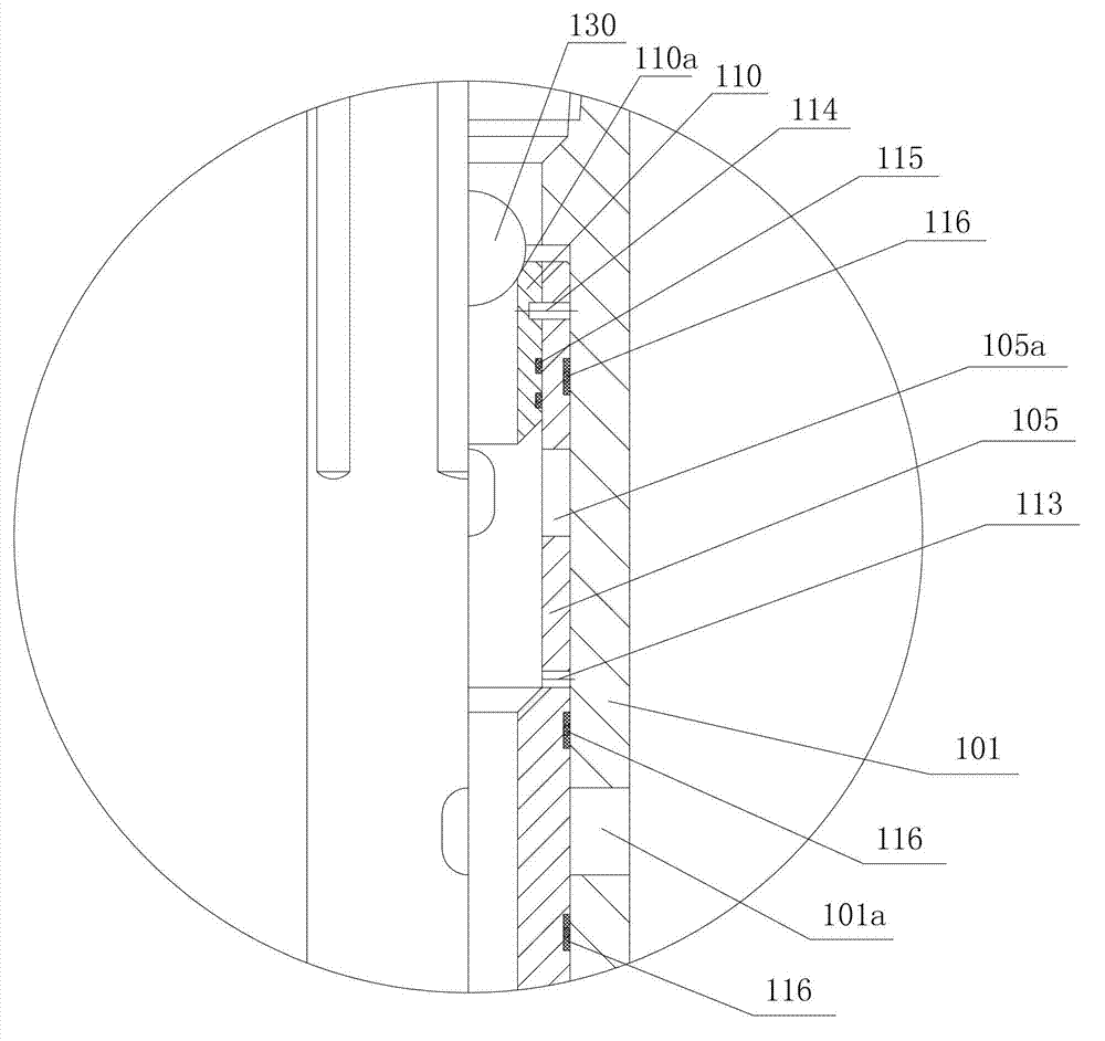
[0035] The invention provides a reasonable and compact hydraulic switch valve, such as figure 2 As shown, the prisoner has a longer axial dimension, in order to clearly reflect the structure of each part, the figure 2 The part of the ball seat sleeve and the ball valve assembly are respectively enlarged as shown in image 3 and Figure 4 shown. Please refer to the following Figure 2 ~ Figure 4 , the hydraulic switching valve 1 of the present invention is connected to the downhole test pipe string, and is a multi-layer hollow tubular body, which has an outer layer, a middle layer and an inner layer in the radial direction, and the outer layer is connected from top to bottom in the axial direction There are an upper joint 101, an i...


PUM


Abstract

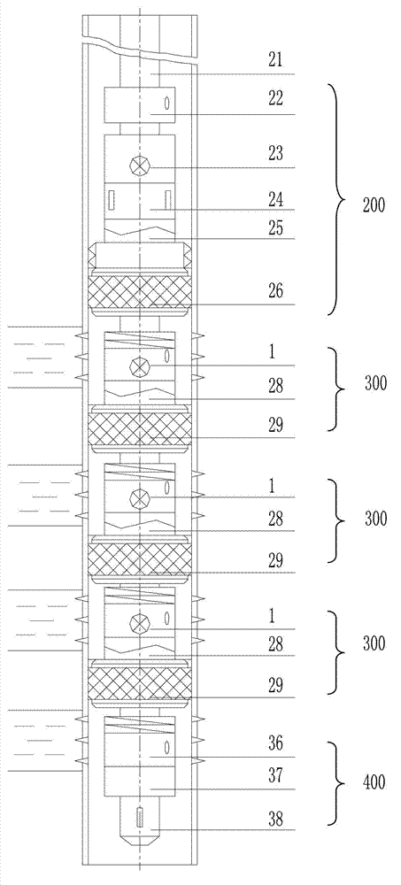
The invention relates to a multi-layer multi-section continuous oil testing system without lifting a tubular column. The system is connected on the downhole testing tubular column in series and comprises an upper sub-system, a plurality of layered testing systems and a lower sub-system which are sequentially connected in series along the axial direction of the tubular column, wherein the upper sub-system comprises a manifold circulating valve, a main testing valve, a full-bore pressure gage support barrel, a safe connector and a top hydraulic packer which are sequentially connected in series along the axial direction of the tubular column. The plurality of layered testing systems are sequentially connected on the tubular column in series along the axial direction of the tubular column, each layered testing system corresponds to one oil layer, and each layered testing system comprises a hydraulic switching valve, a safe connector and a layered hydraulic packer. The lower sub-system comprises a hydraulic sliding sleeve, a pressure transmitting connector and a monitoring pressure gage which are sequentially connected in series along the axial direction of the tubular column. By means of the system, multi-layer and multi-section continuous testing, capacity increasing revamp, liquid discharging and a series of downhole operation processes can be completed without lifting the tubular column, and the system has the advantages of being simple in construction operation, convenient to assemble, short in construction period and the like.

Description

technical field [0001] The invention relates to a multi-layer testing, injection and production tool for oil and gas wells, in particular to a multi-layer continuous oil testing system without running down the pipe string and its operating method. Background technique [0002] In the oil (gas) well, there are multiple perforated intervals that need to obtain oil test data separately, so layered oil test is required. The traditional layered oil testing method uses lower bridge plugs or cement plugs to seal the tested layers, and then goes back to the upper layer layer by layer for oil testing. Its disadvantages are that the pipe strings and bridge plugs (or cement injection plugs) are lowered many times, the construction period is long, the speed is slow, the cost is high, and the oil and gas layers are easily polluted. [0003] US Patent No. 2006 / 0207764 discloses an example of a multi-layer test, injection, production system. This patent relates to an assembly that enable...

Claims


Application Information

Patent Timeline
Patent Type & Authority Applications(China)
IPC IPC(8): E21B47/00E21B43/14E21B34/14
Inventor 张友义孟庆昆刘新云胡贵王向东
Owner PETROCHINA CO LTD
Learn More