
Energy conservation time synchronization method of wireless temperature detecting net

A time synchronization and wireless temperature measurement technology, applied in synchronization devices, wireless communication, energy-saving ICT, etc., can solve the problems of low precision, low precision, and high power consumption, which cannot meet the design requirements of low network power consumption.

Active Publication Date: 2013-10-30
陈鹏
View PDF4 Cites 0 Cited by
  • Summary
  • Abstract
  • Description
  • Claims
  • Application Information

AI Technical Summary

Problems solved by technology

The usual solution is to use a real-time clock chip with temperature compensation to compensate the frequency error of the crystal oscillator caused by temperature, and correct the local clock of the node to achieve time synchronization. At the same time, the calibration of the clock is based on a single node, the accuracy is not high, and it cannot achieve real synchronization with the nodes of the entire network
[0018] From the above, it can be known that due to the limitations of the working environment of the wireless temperature measurement network and the factors of the network and the nodes themselves, the existing time synchronization method is not suitable for the network, and the existing time synchronization method has low accuracy and poor performance. Disadvantages such as high consumption

Method used

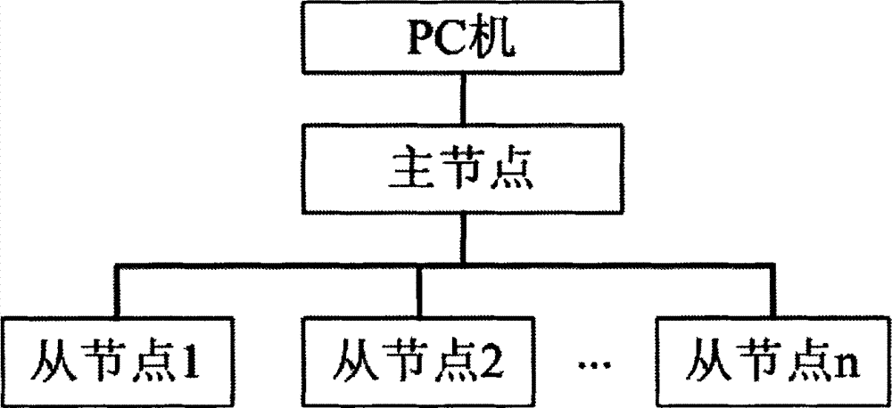
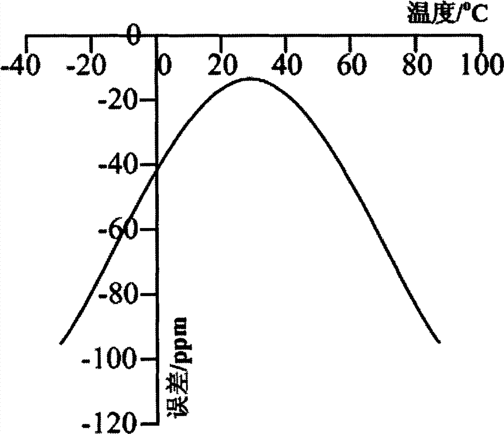
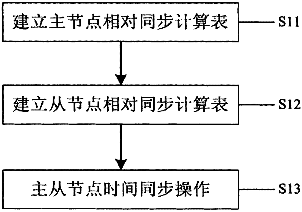

Image

  • Energy conservation time synchronization method of wireless temperature detecting net
  • Energy conservation time synchronization method of wireless temperature detecting net
  • Energy conservation time synchronization method of wireless temperature detecting net

Examples


Embodiment Construction

[0054] In order to achieve the above-mentioned purpose, features and advantages of the present invention to be more obvious and understandable, the specific implementation manners of the present invention will be described in detail below in conjunction with the accompanying drawings. In the following description, the specific implementation details of the present invention are elaborated in order to fully understand the present invention. Those skilled in the art can make similar extensions without departing from the connotation of the present invention. Therefore, the present invention is not limited by the specific modes disclosed below.

[0055] As described in the background technology, for wireless temperature measurement network nodes using the same batch of crystal oscillators, the main factor affecting the deviation of the local clock is caused by the error of the crystal oscillator, and there is a synchronization problem with the existing time synchronization technol...


PUM


Abstract

The invention provides an energy conservation time synchronization method of a wireless temperature detecting net. The energy conservation time synchronization method comprises that step one, a master node relative synchronization computation table is created; step two, a slave node relative synchronization computation table is created; and step three, time synchronization operation of a master node and slave nodes is achieved. According to the energy conservation time synchronization method, on one hand, network node clock errors caused by the aging rate of a crystal oscillator are eliminated, on the other hand, network node clock errors caused by the frequency error of the crystal oscillator are eliminated, meanwhile network repeat synchronization is reduced as far as possible on the basis that network reliable synchronization is guaranteed, synchronization precision is improved, synchronization efficiency is also improved, robustness of a network is improved, and the energy conservation time synchronization method is high in precision, low in power consumption, convenient to use, fast, and capable of being suitable for the wireless temperature detecting net.

Description

technical field [0001] The invention relates to the technical field of wireless sensor networks, in particular to an energy-saving time synchronization method for a wireless temperature measuring network. Background technique [0002] Wireless sensor network (Wireless Sensor Networks, WSN) is a wireless network composed of a large number of stationary or mobile sensor nodes arranged in the monitoring area in a self-organizing and multi-hop manner. Acquisition, processing and transmission. [0003] Low Rate Wireless Personal Area Networks (LR-WPAN), as an important branch of wireless sensor networks, is a wireless network with a relatively small coverage area. An emerging wireless communication network technology proposed for group and wireless seamless connection. It can effectively solve the problem of "the last few meters of cable", so as to carry out wireless networking to the end. [0004] Among them, one node device is used as the master control, and other node devic...

Claims


Application Information

Patent Timeline
Patent Type & Authority Patents(China)
IPC IPC(8): H04W56/00
CPCY02B60/50Y02D30/70
Inventor 陈鹏刘力
Owner 陈鹏
Learn More