
Transmission system with permanent magnet speed regulation clutch

A technology of transmission system and permanent magnet speed regulation, applied in the field of transmission system, can solve the problems of reducing motor life, damage to motor insulation, and large impact of load equipment, and achieve the effect of reducing rotational inertia, prolonging motor life and avoiding burnout.

Inactive Publication Date: 2013-05-08
上海曜中能源科技有限公司
View PDF8 Cites 14 Cited by
  • Summary
  • Abstract
  • Description
  • Claims
  • Application Information

AI Technical Summary

Problems solved by technology

[0003] However, this transmission system also has many technical problems.
[0004] 1. The traditional motor adopts a hard start method. The large current at start-up has a large impact on the grid, which affects the quality of power supply of the grid; damages the motor insulation and reduces the life of the motor; produces a large impact on the motor stator coil and rotor squirrel cage, It will cause the motor to be tight, the coil to be deformed, and the squirrel cage to be broken, etc.
[0005] 2. Overload protection cannot be realized. When the load power of the motor exceeds its rated power, the motor is likely to burn out due to its internal current being too large
[0006] 3. When the motor is hard started, it will have a greater impact on the load equipment and affect the service life
[0007] 4. Due to the hard connection between the motor and the load, the vibration of the load will be transmitted to the motor, which will affect the service life of the motor
[0008] It can be seen from the above that the motor drive system in the prior art has problems such as hard start, no overload protection and short life, which limit its application in demanding occasions
[0009] Clutches are also common in transmission systems. Clutches can be divided into electromagnetic clutches, magnetic powder clutches, friction clutches, and hydraulic clutches. They mainly refer to the combination or separation of the driven part and the active part when the active part is running. In the existing technology, there are few products that combine clutch and speed regulation

Method used


Image

  • Transmission system with permanent magnet speed regulation clutch
  • Transmission system with permanent magnet speed regulation clutch
  • Transmission system with permanent magnet speed regulation clutch

Examples


Embodiment Construction

[0027] The present invention will be described in further detail below in conjunction with the accompanying drawings and specific embodiments, so that those skilled in the art can more clearly understand other advantages and effects of the present invention.

[0028] It should be noted that the structures, proportions, sizes, etc. shown in the drawings of the specification are only used to cooperate with specific implementation methods, so that those skilled in the art can understand the concept of the present invention more clearly, and are not intended to limit the scope of protection of the present invention. . Any structural modification, change in proportional relationship or size adjustment should still fall within the protection scope of the present invention, provided that it does not affect the function and purpose of the present invention. For ease of description, the relative positional relationship of each component is described according to the layout of the drawi...


PUM


Abstract

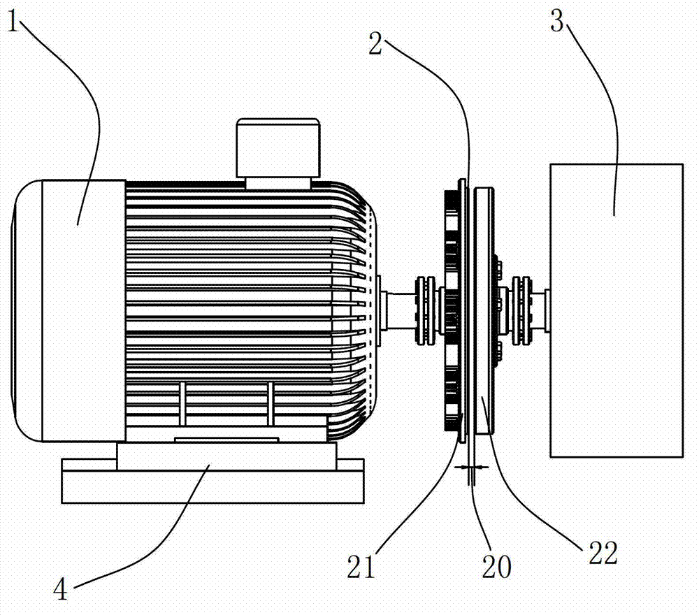
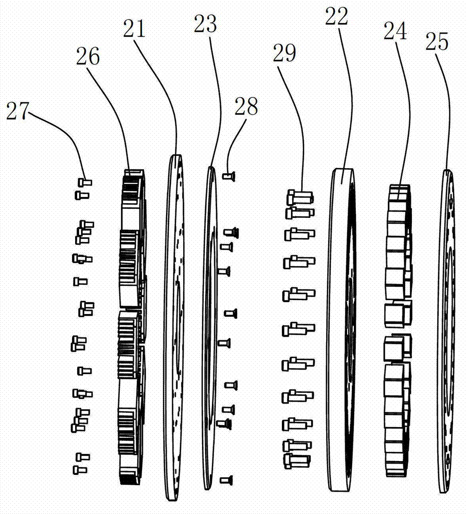
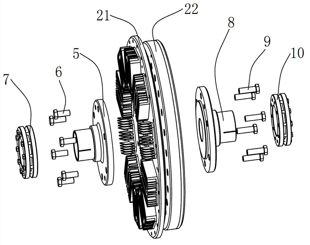
The invention discloses a transmission system with a permanent magnet speed regulation clutch. The transmission system comprises a motor, a clutch and load equipment. A driving disk of the clutch is connected with an output shaft of the motor, a driven disk of the clutch is connected with an input shaft of the load equipment, a conductor disk is fixedly installed on the front side of the driving disk, a permanent magnet is fixedly installed on the driven disk, a magnetic pole of the permanent magnet is positioned on the front side of the driven disk, the front side of the driving disk and the front side of the driven disk are coaxially and oppositely arranged and are not contacted, a gap is positioned between the conductor disk and the magnetic pole of the permanent magnet, and the motor or the load equipment is positioned on the adjustable slide base. The transmission system ahs the advantages of being soft-start, capable of prevent rotation plug, capable of reducing vibration, capable of regulating speed, simple in structure, easy to install and the like.

Description

technical field [0001] The invention relates to a transmission system, in particular to a transmission system with a permanent magnet speed regulating clutch. Background technique [0002] In the transmission system composed of the load equipment and the motor, the most common connection between the load equipment and the motor is a hard connection, that is, the motor shaft is connected to the input shaft of the load equipment through a coupling. It has the following characteristics: 1) High rigidity, high torque, low inertia; 2) Large torque load, high torque rigidity and excellent sensitivity; 3) Zero backlash, same clockwise and counterclockwise rotation characteristics; 4) Maintenance-free , Super oil resistance and corrosion resistance. [0003] But this transmission system also has many technical problems. [0004] 1. The traditional motor adopts a hard start method. The large current at start-up has a large impact on the grid, which affects the quality of power supp...

Claims


Application Information

Patent Timeline
Patent Type & Authority Applications(China)
IPC IPC(8): H02K51/00H02K49/10
Inventor 黄晓兵杜毅
Owner 上海曜中能源科技有限公司
Learn More