Electronic circuit, method of manufacturing electronic circuit, and mounting part
A technology for electronic circuits and mounting parts, applied in the directions of printed circuit components, circuit devices, circuits, etc., can solve the problem of increasing the size of the circuit, and achieve the effect of suppressing the increase in the size of the circuit and transmitting high-quality data
- Summary
- Abstract
- Description
- Claims
- Application Information
AI Technical Summary
Problems solved by technology
Method used
Image

Examples
no. 1 example
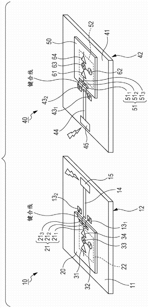
[0123] Figure 4 is a perspective view showing a structural example of a first example of an electronic circuit using an embodiment of the present invention, Figure 5 yes Figure 4 A cross-sectional view of the single-ended I / F 111 portion of the electronic circuit.
[0124] exist Figure 4 and 5 In this example, the electronic circuit includes a mounting part 101 and a millimeter wave transmission chip 110 .
[0125] and figure 1 Similar to the mounting portion 11 of , for example, the mounting portion 101 is a component (mounting component) such as a planar adapter or a printed board, and a semiconductor chip is mounted on the mounting portion 101 .
[0126] A millimeter-wave transmission chip 110 , which is a semiconductor chip, is mounted on the front surface of the flat-plate-shaped mounting portion 101 (ie, one surface of the flat-shaped mounting portion 101 ).
[0127] Here, although a metal film-shaped ground metal (as a ground wire) is provided on the back surf...
no. 2 example
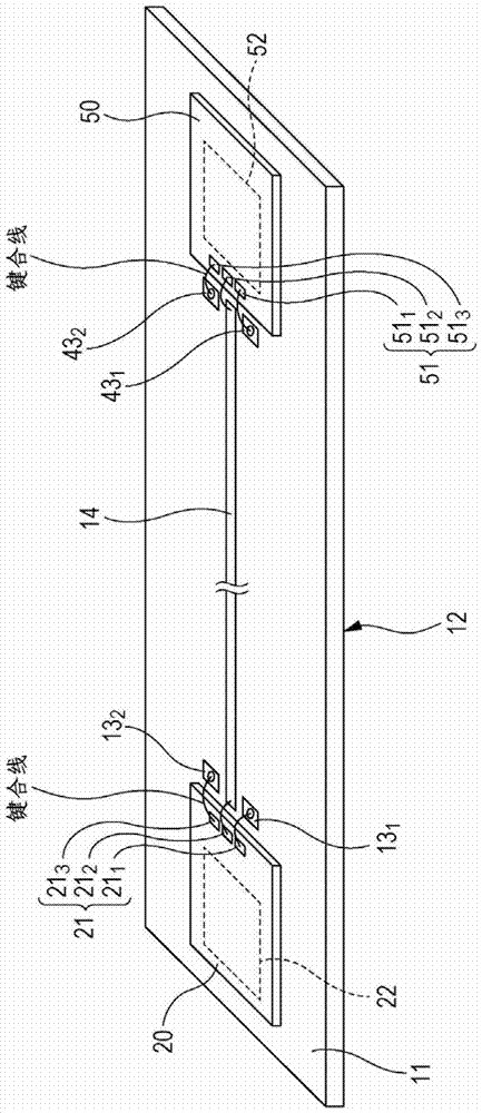
[0152] Figure 6 is a perspective view showing a structural example of a second example of an electronic circuit using an embodiment of the present invention, Figure 7 yes Figure 6 A cross-sectional view of the single-ended I / F 111 portion of the electronic circuit.
[0153] here, in Figure 6 and 7 , the same reference numerals are used to denote the same Figure 4 and Figure 5 Parts corresponding to the first embodiment of the present invention, and their descriptions are appropriately omitted below.
[0154] Figure 6 and 7 The second embodiment of Figure 4 and 5 The difference of the first embodiment is that: the single-ended I / F 111 includes 111 1 and 111 2 These two pads are used instead of 111 1 、111 2 and 111 3 These three pads serve as terminals of the RF section for exchanging single-ended signals.
[0155] The single-ended I / F 111 includes pads 111 1 and pad 111 2 The case of these two pads, with the inclusion of pad 111 1 to 111 3 The situati...
no. 3 example
[0195] therefore, Figure 10 It is a perspective view showing a configuration example of a third example of an electronic circuit using an embodiment of the present invention.
[0196] here, in Figure 10 , the same reference numerals are used to denote the same Figure 4 The parts corresponding to the case of the first embodiment of the present invention, and their descriptions are appropriately omitted hereinafter.
[0197] Figure 10 The third embodiment of Figure 4 The difference in the case of the above is that a dielectric 130 is arranged on the coplanar strip-shaped printed line 103 .
[0198] The dielectric 130 is a dielectric having a dielectric constant greater than that of the mounting portion 101 (for example, a dielectric having a dielectric constant of about 10), and by arranging a dielectric having such a large dielectric constant on the coplanar strip printed line 103 130, it is possible to make the impedance Z of the coplanar strip-shaped printed line 10...
PUM
| Property | Measurement | Unit |
|---|---|---|
| relative permittivity | aaaaa | aaaaa |
| relative permittivity | aaaaa | aaaaa |
| relative permittivity | aaaaa | aaaaa |
Abstract
Description
Claims
Application Information
 - R&D
- Intellectual Property
- Life Sciences
- Materials
- Tech Scout
- Unparalleled Data Quality
- Higher Quality Content
- 60% Fewer Hallucinations
Browse by: Latest US Patents, China's latest patents, Technical Efficacy Thesaurus, Application Domain, Technology Topic, Popular Technical Reports.
© 2025 PatSnap. All rights reserved.Legal|Privacy policy|Modern Slavery Act Transparency Statement|Sitemap|About US| Contact US: help@patsnap.com