
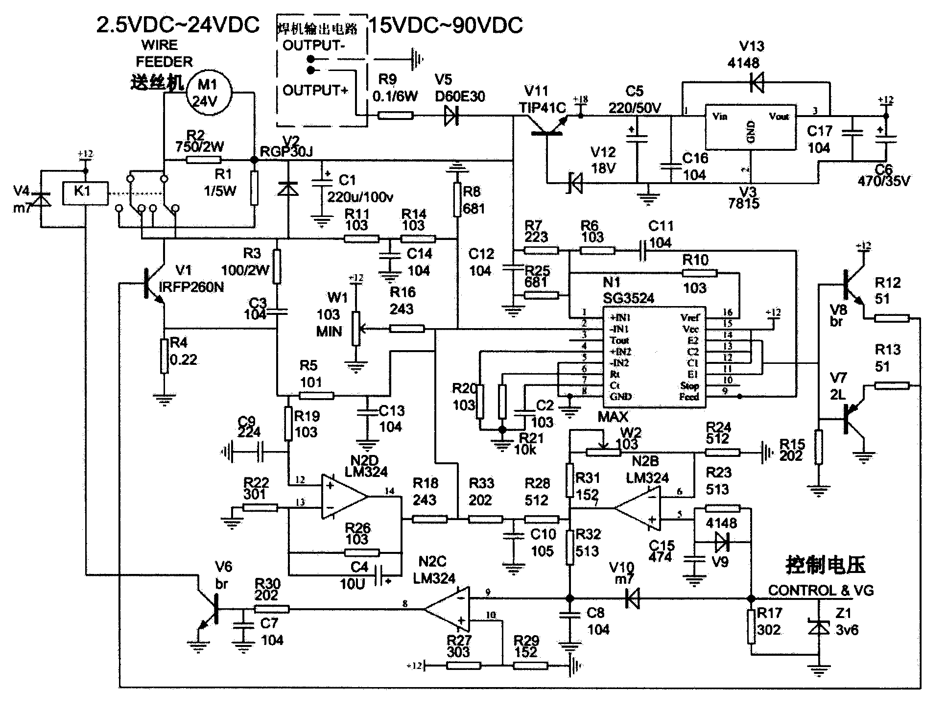
Wire feeder control circuit

A technology for controlling circuits and wire feeders, used in manufacturing tools, arc welding equipment, welding equipment, etc., can solve the problems of easy soldering, difficulty in changing speed, adhesion, etc., to reduce welding spatter, improve welding The effect of output efficiency

Active Publication Date: 2014-07-30
NANTONG FREE MECHANTRONIC CO LTD
View PDF5 Cites 0 Cited by
  • Summary
  • Abstract
  • Description
  • Claims
  • Application Information

AI Technical Summary

Problems solved by technology

[0002] When performing large-scale welding, a large amount of welding wire needs to be used. Manual wire feeding obviously cannot keep up with the welding speed, so it is necessary to use a wire feeder for wire feeding. The actual situation is different, and the wire feeding speed is also different. If the speed is too fast, then The welding wire will stick to the workpiece and it is difficult to remove; if the speed is too slow, the solder will be insufficient and easy to weld. Environmental protection; and the transformer is heavy and inconvenient to carry

Method used


Image

  • Wire feeder control circuit

Examples


Embodiment Construction

[0012] Below in conjunction with accompanying drawing, the present invention is further described in detail:

[0013] The invention relates to a control circuit of a wire feeder, including a power supply, a single-chip microcomputer, and a wire feeder. The power supply: the output voltage (arc voltage) of the welding machine is used as an energy source to provide the voltage of the wire feeder, which overcomes the need to use a lot of power The large industrial frequency transformer is insufficient as the power supply of the wire feeder, which saves energy, materials and weight.

[0014] The output voltage of the welding machine is rectified and filtered by V5 and C1, and divided into two circuits. One path is used as the main power supply for the wire feeder; the other path provides +18V and +12V through V11 and V12, and is used as the power supply for the control circuit.

[0015] The control voltage is added to pin ⑨ of N2LM324 through V10, and compared with the voltage of...


PUM


Abstract

The invention relates to a wire feeder control circuit. The wire feeder control circuit comprises a power source, a single chip microcomputer and a wire feeder. Output voltage of the power source is output voltage of a welding machine, is rectified and filtered through V5 and C1 and is divided into two branches. One branch of the output voltage is used by the power source as a main power source. The other branch of the output voltage passes through V11 and V12 and provides direct current of +18V and +12V as a power source of a control loop. The power source is connected with an end 1 of the single chip microcomputer through R7, and ends from 11 to 14 of the single chip microcomputer are connected with the wire feeder after passing through V7, V8, R12, R13 and V1. Compared with the prior art, arc voltage of the welding machine is used as the power source, high and low states of the arc voltage limit the upper limit of wire feeding speed at the same time, and welding wires can be prevented from being bonded to work-pieces effectively. The wire feeding speed disturbs along with changes of the arc voltage, melting point transition is benefited, welding spatter is reduced, and welding forming is improved. Besides, output efficiency of the welding machine is improved, cost is reduced, and a wire feeding circuit can be arranged in an integrated machine and can be arranged in the wire feeder, and is not restrained by the length of connecting wires.

Description

technical field [0001] The invention relates to a control circuit, specifically, a control circuit of a wire feeder. Background technique [0002] When performing large-scale welding, a large amount of welding wire needs to be used. Manual wire feeding obviously cannot keep up with the welding speed, so it is necessary to use a wire feeder for wire feeding. The actual situation is different, and the wire feeding speed is also different. If the speed is too fast, then The welding wire will stick to the workpiece and it is difficult to remove; if the speed is too slow, the solder will be insufficient and easy to weld. Environmental protection; and the transformer is heavy and inconvenient to carry. Contents of the invention [0003] Purpose of the invention: The purpose of the invention is to provide a control circuit with light weight, variable speed, energy saving and environmental protection to replace the traditional transformer. [0004] Technical solution: The presen...

Claims


Application Information

Patent Timeline
Patent Type & Authority Patents(China)
IPC IPC(8): B23K9/095B23K9/133
Inventor 蒋林祥吴建中
Owner NANTONG FREE MECHANTRONIC CO LTD
Learn More