Eureka AIR delivers breakthrough ideas for toughest innovation challenges, trusted by R&D personnel around the world.

Ejector pin device of die grading equipment

A thimble and sorting technology, which is applied in the manufacture of electrical components, semiconductor/solid-state devices, circuits, etc., can solve the problems of chip suction failure, inconvenient replacement of thimbles, poor chip arrangement accuracy, etc., to achieve stable performance and improve sorting Good quality, success rate and repeatability

Inactive Publication Date: 2013-05-01
广东志成华科光电设备有限公司
View PDF4 Cites 8 Cited by
  • Summary
  • Abstract
  • Description
  • Claims
  • Application Information

AI Technical Summary

Problems solved by technology

[0004] When the existing thimble device is working, due to the error in machining, the thimble and the axis of the hole on the thimble sleeve for the thimble to pass through are not concentric, so that the thimble is biased to one side, resulting in the thimble not being able to lift the chip from the center of the chip. Poor chip arrangement accuracy or chip suction failure; due to the fixed thimble device, the movement stroke of the supply cylindrical platform is limited, but other functions require the supply cylindrical platform to have a large moving distance, so that the inner wall of the cylindrical platform Interference with the thimble sleeve; In addition, it is not very convenient to replace the thimble with the existing thimble device

Method used


Image

  • Ejector pin device of die grading equipment
  • Ejector pin device of die grading equipment
  • Ejector pin device of die grading equipment

Examples


Embodiment Construction

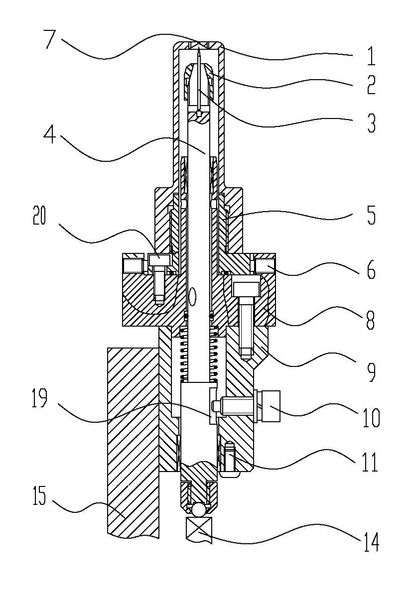
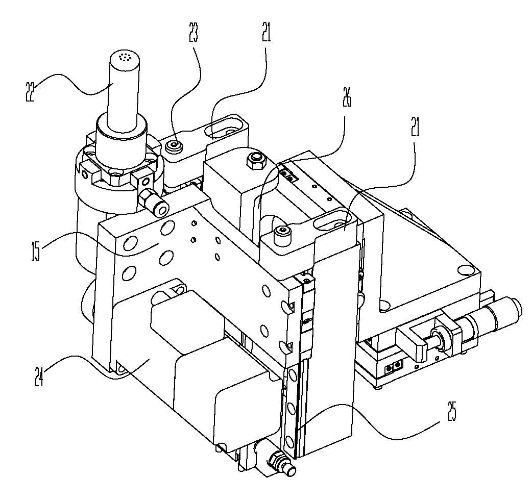
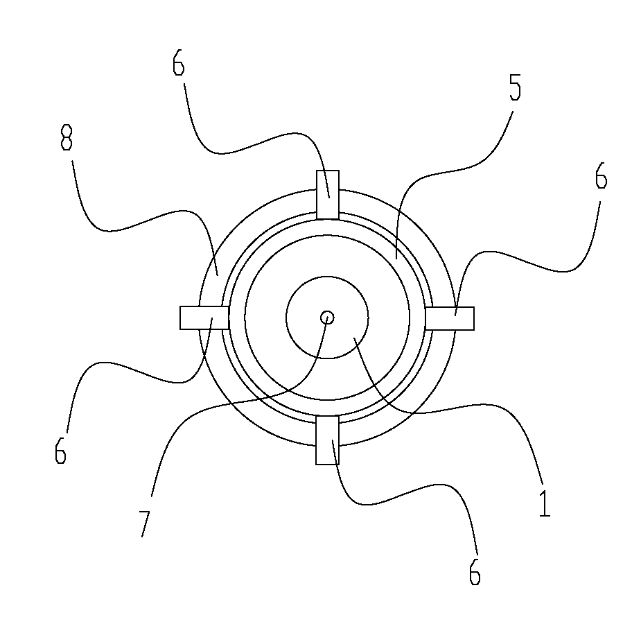
[0040] The preferred embodiments of the present invention will be described below in conjunction with the accompanying drawings. It should be understood that the preferred embodiments described here are only used to illustrate and explain the present invention, and are not intended to limit the present invention.

[0041] Such as Figure 1 to Figure 3 As shown, a thimble device for chip sorting equipment according to the present invention includes a thimble sleeve 1, a thimble shaft 4 and a mounting seat. The thimble 3 and the thimble shaft 4 are connected with a thimble shaft driving device 22 that drives the thimble shaft 4 to move up and down. The thimble sleeve 1 is provided with a thimble hole 7 for the thimble 3 to pass through. The adjustment seat 5 for adjusting the position of the thimble sleeve 1, the thimble sleeve 1 is fixedly connected to the adjustment seat 5, and connection methods such as clamping connection, screw connection, and screw connection can be adopte...


PUM


Abstract

The invention discloses an ejector pin device of die grading equipment, which comprises an ejector pin sleeve, an ejector pin shaft and an installing seat, wherein the liftable ejector pin shaft is arranged in the ejector pin sleeve; an ejector pin is fixedly arranged on a top end of the ejector pin shaft; the ejector pin shaft is connected with an ejector pin shaft drive device for driving the ejector pin shaft to move up and down; an ejector pin hole for the ejector pin to penetrate through is arranged in the ejector pin sleeve; an adjusting seat for adjusting the position of the ejector pin sleeve is also sleeved on an outer side of the ejector pin shaft; the ejector sleeve is fixedly connected with the adjusting seat; and the adjusting seat is fixedly connected with the installing seat. According to the ejector pin device, through adjusting the position of the adjusting seat, the ejector pin sleeve is driven to move, so that axial lines of the ejector pin and the ejector pin hole can be adjusted to be coaxial basically, and the array accuracy of chips is greatly improved; and the ejector pin can be replaced conveniently and quickly, the ejector pin can be replaced through disassembling the ejector pin sleeve, after the ejector pin is replaced, the position of the adjusting seat is adjusted through a lens so as to drive the ejector pin sleeve to move, and the ejector pin and the ejector pin hole for the ejector pin to penetrate through of the ejector pin sleeve are observed to be adjusted so as to be coaxial.

Description

technical field [0001] The invention belongs to the technical field of semiconductor chip testing and sorting devices, and in particular relates to a thimble device for chip sorting equipment. Background technique [0002] The function of the chip sorting equipment is to sort and discharge the chips. During the working process, the chips to be sorted are evenly pasted on the flip film, and the flip film is tightened and fixed on the nylon ring (that is, the mother ring) that is closely matched by the inner and outer rings. The mother ring is installed on the XY direction. On the supply cylindrical platform that moves and rotates 30° around its own axis, the scanning CCD system on the upper part of the platform identifies and locates each chip on the flip film. The chip transfer system grabs each chip and places it on the receiving platform according to the rules to complete chip sorting. [0003] The thimble device is an important component of the chip sorting equipment. I...

Claims


Application Information

Patent Timeline
Patent Type & Authority Applications(China)
IPC IPC(8): H01L21/687
Inventor 朱国文吴涛龚时华朱文凯贺松平李斌吴磊宋宪振黄惠
Owner 广东志成华科光电设备有限公司
Why Eureka
Eureka Blog
Learn More