
Contactor coil

A technology of contactors and coils, applied in the direction of relays, electromagnetic relays, detailed information of electromagnetic relays, etc., can solve the problems of irregular shape of the wire package, prone to noise, open circuit or short circuit of the coil, etc., and achieve good waterproof performance and not easy to leak , good isolation effect

Active Publication Date: 2013-05-01
NINGBO ZHONGCE E T ELECTRONICS
View PDF7 Cites 1 Cited by
  • Summary
  • Abstract
  • Description
  • Claims
  • Application Information

AI Technical Summary

Problems solved by technology

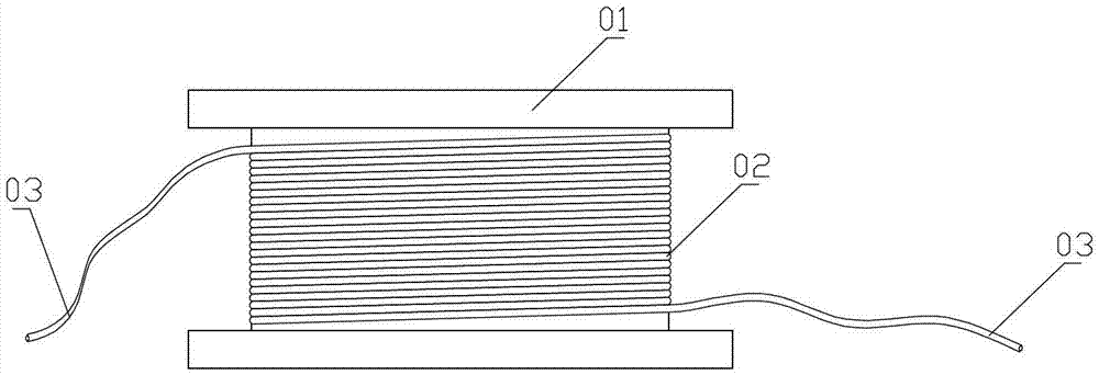
The contactor coil with the above structure has the following disadvantages: 1. The enameled wire 02 lacks effective protection. When the contactor works under strong vibration or collides with other metal parts, the enameled wire 02 is prone to damage and causes the coil to break or short circuit.
2. The enameled wire 02 is directly exposed or only wrapped with a simple insulating tape, and the waterproof performance is poor. When the contactor works in a humid environment for a long time, the enameled wire 02 is prone to leakage
3. When the coil is working, there is no effective isolation, and it is prone to noise after power-on
4. When the coil is installed, due to the irregular shape of the wire package wound by the enameled wire 02, the safety distance between it and other components is not easy to control, so that other surrounding components must maintain a large distance from it. limitation

Method used


Image

  • Contactor coil
  • Contactor coil
  • Contactor coil

Examples


Embodiment Construction

[0020] The present invention will be described in further detail below in conjunction with the accompanying drawings.

[0021] combined with image 3 to attach Figure 5 , a contactor coil, which includes at least one winding unit, the winding unit includes a skeleton 1 and an enameled wire 2, and the enameled wire 2 is wound on the skeleton 1; it is characterized in that: the enameled wire 2 is covered There is an insulating layer 3 that seals the enameled wire 2, and the starting and ending wire ends of the enameled wire 2 are provided with wiring structures protruding from the insulating layer. . The thickness of the insulating layer 3 is not less than 0.7 mm. The thickness of the insulating layer 3 stated as a best practice value is 1 mm. The insulating layer 3 is integrally formed by die casting of polyethylene terephthalate insulating material. The polyethylene terephthalate insulation material is obtained by condensation polymerization of terephthalic acid and ethy...


PUM

PropertyMeasurementUnit
Thicknessaaaaaaaaaa
Thicknessaaaaaaaaaa

Abstract

The invention relates to a contactor coil, which at least comprises a winding unit. The winding unit comprises a framework (1) and an enamelled wire (2), and the enamelled wire (2) is twined on the framework (1). The contactor coil is characterized in that an insulating layer (3) sealing the enamelled wire (2) covers outside the enamelled wire (2), and both a starting thread end and an ending thread end of the enamelled wire (2) are provided with a wiring structure stretching out of the insulating layer. The invention provides a contactor coil which can prevent water and vibration, causes low work noise, hardly leaks electricity, and has small spatial arrangement limitation when in use.

Description

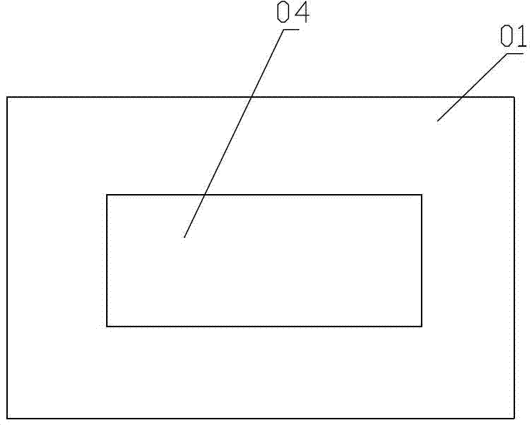
technical field [0001] The invention relates to the technical field of contactor accessories, in particular to a contactor coil. Background technique [0002] In a broad sense, a contactor refers to an electrical appliance that uses a current flowing through a coil to generate a magnetic field in industrial electronic control technology to close the contacts to control the load. The contactor is composed of electromagnetic system (iron core, electromagnetic coil), contact system (normally open contact and normally closed contact) and arc extinguishing device. It is widely used in the control field of electrical equipment. The coil is an important accessory of the contactor. In the prior art, the contactor coil mostly adopts the attached figure 1 And attached figure 2 The structure shown in , it includes a skeleton 01 and an enameled wire 02 wound on the skeleton 01, many of the enameled wires 02 are as attached figure 1 In the case, it is directly exposed outside, and ...

Claims


Application Information

Patent Timeline
IPC IPC(8): H01H50/44
Inventor 徐志瑞
Owner NINGBO ZHONGCE E T ELECTRONICS
Learn More