
Key cap drawing force testing device for thin keyboard

A testing device and technology of pulling force, which is applied in the field of key cap pulling force testing device, can solve the problems of inability to distinguish the force supply, affect the service life of the vacuum pump, and small space, and achieve the effect of avoiding work influence

Inactive Publication Date: 2013-05-01
KUNSHAN HONGZHIXI AUTOMATION EQUIP
View PDF4 Cites 6 Cited by
  • Summary
  • Abstract
  • Description
  • Claims
  • Application Information

AI Technical Summary

Problems solved by technology

[0005] (1) There is a negative pressure state before the vacuum pump is started. When the vacuum pump is started to work, because there is no negative pressure relief mechanism, it will cause damage to the vacuum pump and affect the service life of the vacuum pump;
[0006] (2) The vacuum chamber of the vacuum pump has a small space, and there are many sucker air paths separated by the flow divider. Once there is an air leak in one of the air paths, it will have a very serious impact on the pressure in the vacuum chamber and affect other air paths. normal work;
[0007] (3) Since the air path of the suction cup is always inhaled, other impurities in the air will be easily sucked into the air path of the suction cup during the suction process, which is difficult to clean;
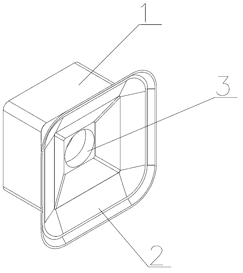
[0008] (4) The suction cup is a circular suction cup, and the keycap is square, so the surface on which the keycap is adsorbed is very limited; and the test force range of the keycap is on the circular area where the surface of the keycap is adsorbed by the circular suction cup, while The buckle points of the keycap are at its four corners, so the test of the keycap is not realistic enough;
[0009] (5) The force provided by all the suction cups is the same. Since the keycaps are different in size, the force cannot be distinguished

Method used


Image

  • Key cap drawing force testing device for thin keyboard
  • Key cap drawing force testing device for thin keyboard
  • Key cap drawing force testing device for thin keyboard

Examples


Embodiment Construction

[0032] The present invention will be further described below in conjunction with the accompanying drawings.

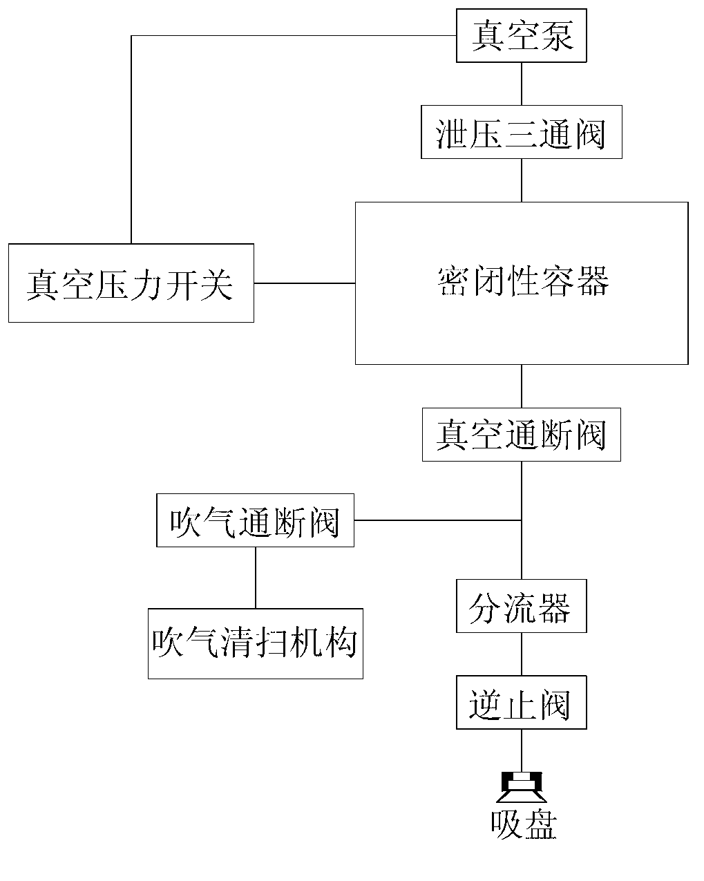
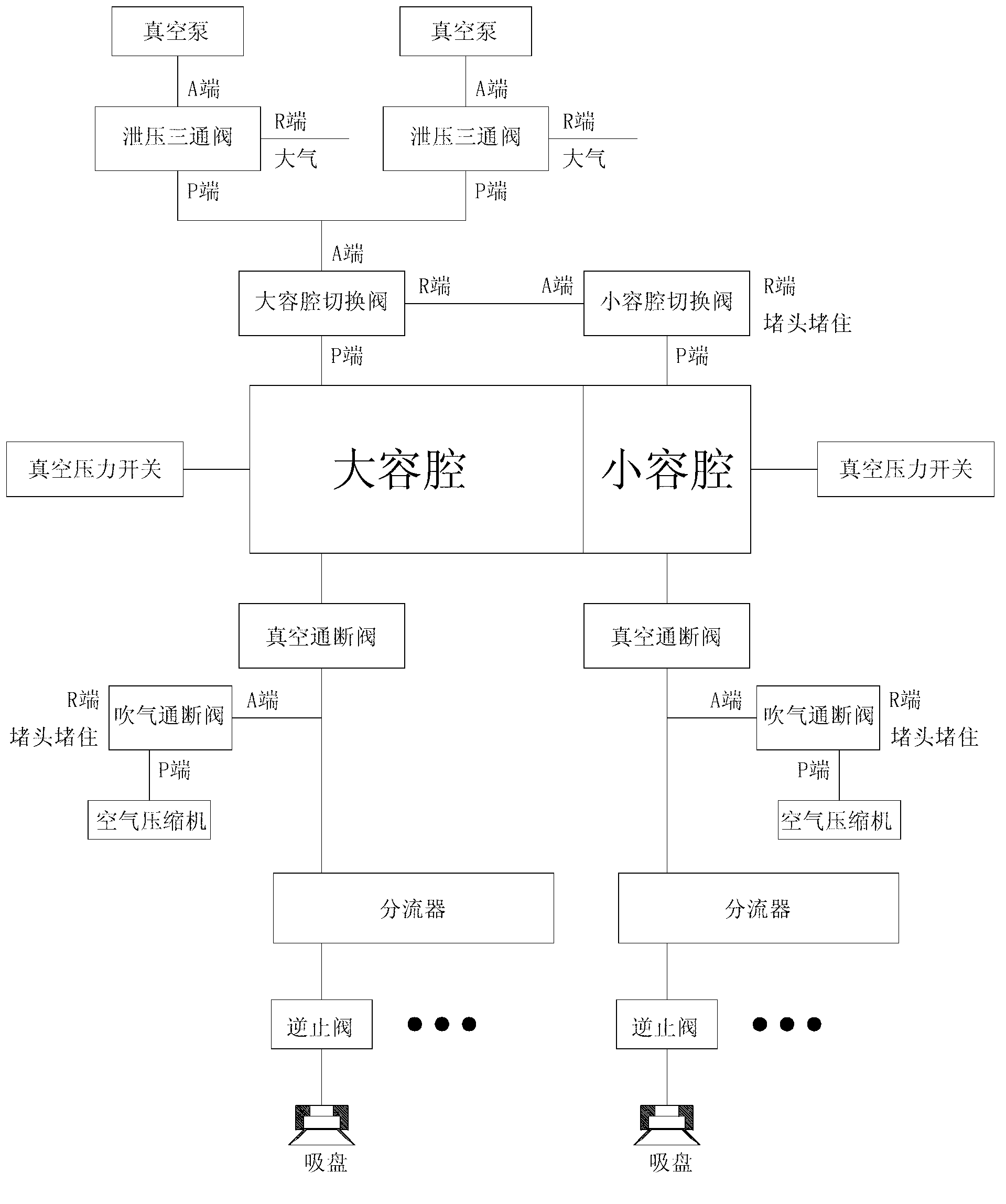
[0033] Such as figure 1 Shown is a thin keyboard keycap pullout test device, including a vacuum pump, pressure relief three-way valve, airtight container, vacuum on-off valve, flow divider, several suction cup air circuits, vacuum pressure switch, blowing and cleaning mechanism and the blowing on-off valve, the suction cup air circuit includes a check valve and a suction cup; the vacuum pump is connected to the A end of the pressure relief three-way valve, the R end of the pressure relief three-way valve is connected to the atmosphere, and the P end of the pressure relief three-way valve is connected to the atmosphere. The end is connected to the vacuum port of the airtight container, and the suction port of the airtight container is connected to the air path of the suction cup through the vacuum on-off valve and the flow divider in turn; the sensing end of the vacuum ...


PUM


Abstract

The invention discloses a key cap drawing force testing device for a thin keyboard. The key cap drawing force testing device comprises vacuum pumps, pressure relief three-way valves, an airtight container, vacuum on-off valves, flow dividers and a plurality of sucking disc air paths. Each sucking disc air path comprises a check valve and a sucking disc. The vacuum pumps are respectively connected with the ports A of the pressure relief three-way valves, the ports R of the pressure relief three-way valves are respectively connected with the atmosphere, the ports P of the pressure relief three-way valves are respectively connected with the vacuum pumping port of the airtight container, and the air suction port of the airtight container is connected with the sucking disc air paths sequentially through the vacuum on-off valves and the flow dividers. The key cap drawing force testing device for the thin keyboard provided by the invention has the advantages that the working of the entire device can be prevented from being influenced by air leakage of a single air path and the vacuum pumps can be protected at the same time.

Description

technical field [0001] The invention relates to a device for testing the pulling force of a keycap of a thin keyboard. Background technique [0002] The thin keyboard includes a key board and a key cap. The circuit structure and keys are arranged on the key board. The key cap is usually snapped on the key board through the buckle structure at the four corners and is located above the corresponding keys. Due to the structural limitations of the thin keyboard, The buckle structure is relatively small, so it is easy to have bad buckle, such as not snapping, insufficient buckle strength, etc., which is reflected in the overall structure of the keyboard, that is, the keycaps are not flush, the keycaps fall off, and the keys are not smooth. In order to reduce or even avoid bad buckling of the keycap, it is necessary to perform a pull-out force test on the keycap after the keycap is installed on the keyboard, that is, to use a certain amount of force perpendicular to the keyboard t...

Claims


Application Information

Patent Timeline
IPC IPC(8): G01M13/00
Inventor 刘利刚
Owner KUNSHAN HONGZHIXI AUTOMATION EQUIP
Learn More