
Dual-refrigerant liquefaction system and method for NG (Natural Gas)

A dual-refrigerant and natural gas technology, which is applied in the natural gas dual-refrigerant liquefaction system and liquefaction field, can solve the problems of the complexity of the liquefaction system, high energy consumption, unstable LNG output, and high energy consumption of the liquefaction system.

Active Publication Date: 2013-05-01
PETROCHINA CO LTD +1
View PDF5 Cites 9 Cited by
  • Summary
  • Abstract
  • Description
  • Claims
  • Application Information

AI Technical Summary

Problems solved by technology

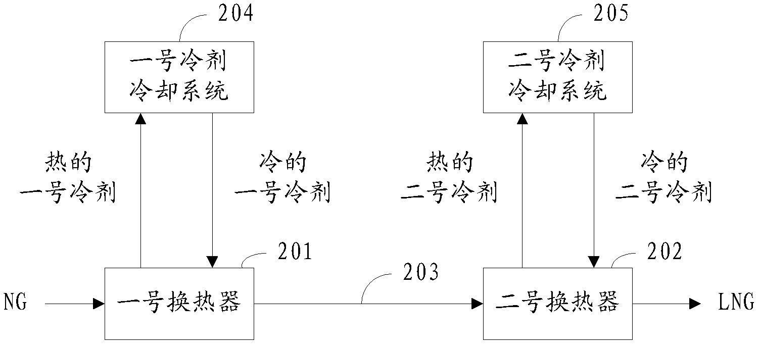
[0006] visible, image 3 The existing mixed refrigerant liquefaction system shown in the figure liquefies NG. At least two cold boxes are required to meet the requirements. The two refrigerants in this technology work independently and are cooled independently, so the complexity of the entire liquefaction system and higher energy consumption
In addition, when the No. 1 refrigerant uses propane, its physical characteristics determine that the lowest temperature it can achieve for NG precooling is a fixed value of about -40°C. Therefore, when the composition of NG changes, or at ambient temperature When changing with the seasons, the LNG output of the liquefaction system will be unstable, especially when the ambient temperature is below -40°C, the liquefaction of NG does not require propane pre-cooling, but if the No. 1 heat exchanger 201 is not used , the whole liquefaction system will not work, so the energy consumption of the liquefaction system is quite large

Method used


Image

  • Dual-refrigerant liquefaction system and method for NG (Natural Gas)
  • Dual-refrigerant liquefaction system and method for NG (Natural Gas)
  • Dual-refrigerant liquefaction system and method for NG (Natural Gas)

Examples


Embodiment Construction

[0049] The structure of the natural gas dual refrigerant liquefaction system according to the present invention will be described in detail below in conjunction with the accompanying drawings.

[0050] Such as Figure 4 As shown, the system includes:

[0051] The dual refrigerant liquefaction system for natural gas includes:

[0052] Deacidification tower 57, dryer 58, mercury removal tank 59, dust filter 60, BOG cooler 62, compressor 61, heat exchanger 54, No. 1 refrigerant external treatment subsystem, No. 1 refrigerant cooling subsystem 01 , No. 2 refrigerant external treatment subsystem, No. 2 refrigerant cooling subsystem 02, heavy hydrocarbon separation tank 23 and denitrification tank 41;

[0053] Among them, the No. 1 refrigerant cooling subsystem 01 includes: NG pre-cooling channel 11, No. 1 refrigerant pre-cooling channel 12, No. 1 refrigerant cooling channel 13 and No. 2 refrigerant first-stage pre-cooling channel 14;

[0054] No. 2 refrigerant cooling subsystem ...


PUM


Abstract

The invention relates to a dual-refrigerant liquefaction system and a dual-refrigerant liquefaction method for NG (Natural Gas). The system comprises a cold box for liquefying the NG, an NG supply pipe, a No.1 refrigerant external treatment subsystem, a No.2 refrigerant external treatment subsystem, a No.1 refrigerant cooling subsystem, a No.2 refrigerant cooling subsystem, a heavy hydrocarbon separation tank which is used for realizing gas-liquid separation of heavy hydrocarbon and light hydrocarbon, and a denitrification tank, wherein the cold box comprises an NG precooling passage which is used for cooling liquid heavy hydrocarbon components and gas light hydrocarbon components obtained through cooling; an NG deep cooling passage which is used for liquefying the gas light hydrocarbon components; a No.1 refrigerant precooling passage which is used for cooling high-pressure normal-temperature No.1 refrigerant; a No.2 refrigerant first section precooling passage and a No.2 refrigerant second section precooling passage which are used for cooling No.2 refrigerant; a No.1 refrigerant cooling passage which is used for cooling the NG, the high-pressure normal-temperature No.1 refrigerant and high-pressure normal-temperature No.2 refrigerant by using low-pressure low-temperature No.1 refrigerant; and a No.2 refrigerant cooling passage which is used for cooling the light hydrocarbon components and the No.2 refrigerant by using low-pressure low-temperature No.2 refrigerant. By adopting the technical scheme, the complexity and the energy consumption of the system can be reduced.

Description

technical field [0001] The invention relates to a natural gas double refrigerant liquefaction system and a liquefaction method. Background technique [0002] Natural gas (NG) is a gaseous substance under ambient conditions, and it is very uneconomical to transport it to users through pipelines over long distances, especially when it is necessary to cross the ocean or cannot lay pipelines. Therefore, to realize the transportation and utilization of natural gas , which must be liquefied into liquefied natural gas (LNG). [0003] The industrial application of natural gas liquefaction technology began in the 1960s. Since its development, the mature natural gas liquefaction process can be divided into three types, namely cascade refrigeration process, expansion refrigeration process and mixed refrigerant refrigeration process. Among them, cascade refrigeration process The circulation process of the process has many units, complicated control, and inconvenient maintenance, so it ...

Claims


Application Information

Patent Timeline
IPC IPC(8): F25J1/02
CPCF25J1/0022F25J1/004F25J1/0052F25J1/0087F25J1/0214F25J1/0216F25J1/0238F25J1/0244F25J1/0292F25J2220/64F25J2245/90
Inventor 白改玲王红宋媛玲吴笛林畅程喜庆李婵李佳孙文强
Owner PETROCHINA CO LTD
Learn More