
Novel reinforced-concrete combined pier column and construction method thereof

A technology of reinforced concrete and construction method, applied in bridge parts, bridge materials, bridges, etc., can solve problems such as failure, degradation of bearing capacity of ordinary reinforced concrete columns, and maintenance of bearing capacity of components, so as to improve concrete strength and enhance earthquake resistance. Performance and repairability, the effect of enhanced seismic performance

Active Publication Date: 2013-05-01
FUZHOU UNIV
View PDF3 Cites 23 Cited by
  • Summary
  • Abstract
  • Description
  • Claims
  • Application Information

AI Technical Summary

Problems solved by technology

The study found that the existing bridge pier structure still has the following problems: (1) When the longitudinal reinforcement of the member yields, the bearing capacity of the member basically remains unchanged or changes little; (2) when the member reaches the ultimate load, the general The bearing capacity of reinforced concrete columns degrades rapidly or even fails
Due to the existence of the above problems, it is not conducive to the reduction of the residual deformation of the pier and the improvement of the ductility.

Method used


Image

  • Novel reinforced-concrete combined pier column and construction method thereof
  • Novel reinforced-concrete combined pier column and construction method thereof
  • Novel reinforced-concrete combined pier column and construction method thereof

Examples


Embodiment 1

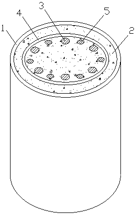
[0023] In Example 1: as figure 1 As shown, six ordinary steel bars 3 and six fiber bars 5 are arranged at equal intervals, and the cross-section of the fiber-reinforced composite material tube 1 is circular.

Embodiment 2

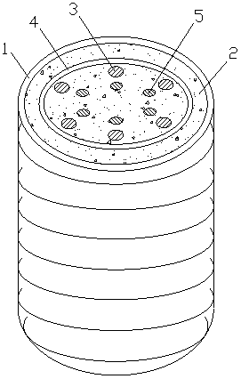
[0024] In Example 2: such as figure 2 As shown, six ordinary steel bars 3 and six fiber bars 5 are arranged in layers, six ordinary steel bars 3 are equally spaced to form an outer ring, and six fiber bars 5 are equally spaced to form an inner ring; the fiber reinforced composite material pipe 1 is composed of Made of unidirectional fiber cloth, the cross-section of the fiber reinforced composite material pipe 1 is circular, and the outer ring and the inner ring are concentric with the fiber reinforced composite material pipe 1 .

Embodiment 3

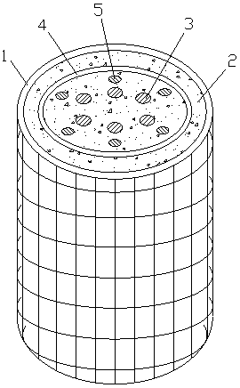
[0025] In Example 3: as image 3 As shown, six ordinary steel bars 3 and six fiber bars 5 are arranged in layers, six ordinary steel bars 3 are equally spaced to form an inner ring, and six fiber bars 5 are equally spaced to form an outer ring; the fiber reinforced composite material pipe 1 is composed of Made of two-way fiber cloth, the cross-section of the fiber reinforced composite material tube 1 is circular, and the outer and inner rings are concentric with the fiber reinforced composite material tube 1 .

[0026] In Example 3: as Figure 4 As shown, four common steel bars 3 and four fiber bars 5 are arranged at equal intervals, the cross-section of the fiber-reinforced composite material tube 1 is rectangular, and the four common steel bars 3 are respectively located at four right angles of the rectangular stirrup 4. The root fiber bars 5 are respectively located at the midpoints of the four sides of the rectangular stirrup 4 .

[0027] In the above embodiment, the fib...


PUM


Abstract

The invention relates to a novel reinforced-concrete combined pier column. The combined pier column comprises a fibre-reinforced composite material pipe, wherein a plurality of common reinforcing steel bars and a plurality of fibre bars are arranged in the fibre-reinforced composite material pipe in a distributing way along the length direction of the fibre-reinforced composite material pipe, these common reinforcing steel bars and these fibre bars are all coiled at the middle part in the fibre-reinforced composite material pipe by a plurality of hooping bars, and concrete is poured in the fibre-reinforced composite material pipe. The invention also relates to a corresponding construction method of the novel reinforced-concrete combined pier column. According to the novel reinforced-concrete combined pier column and the construction method of the novel reinforced-concrete combined pier column, the bearing capacity of a pier column structure can be enhanced; moreover, the shock resisting performance of a pier column and the recoverable performance after shock can be effectively enhanced; furthermore, the self weight of the structure is decreased; and the novel reinforced-concrete combined pier column has the characteristic of corrosion resistance under severe environments, such as ocean, humidity, saline-alkali soil and the like.

Description

technical field [0001] The invention relates to a novel reinforced concrete composite pier column and a construction method thereof, belonging to the technical field of structural engineering. Background technique [0002] Bridge piers are the main components of the bridge structure system to resist the lateral force of the earthquake. The direct damage to the bridge piers and the secondary earthquake damage to the superstructure extended therefrom are the main causes of bridge damage in earthquakes. In an earthquake, not only the severely damaged pier needs to be rebuilt, but also the slightly damaged pier with severe residual deformation needs to be rebuilt because the superstructure is difficult to return to its original position. Therefore, the pier structure not only requires high strength and high ductility, but also requires the residual deformation of the pier to be controlled within an appropriate range after the earthquake, so as to facilitate its usability and rep...

Claims


Application Information

Patent Timeline
Patent Type & Authority Applications(China)
IPC IPC(8): E01D19/02E01D101/24E01D101/26
Inventor 姜绍飞沈圣张崇祥吴兆旗方圣恩
Owner FUZHOU UNIV
Learn More