Thermoforming method and plate assembly thereof

A technology for thermoforming and sheet metal, applied in chemical instruments and methods, lamination, lamination devices, etc., can solve the problems of inability to fully fit the light guide plate process, complicated and other problems, and achieve the solution of labor cost loss, increase yield, The effect of improving the process

Inactive Publication Date: 2013-05-01
CHENMING MOLD IND CORP
View PDF5 Cites 1 Cited by
  • Summary
  • Abstract
  • Description
  • Claims
  • Application Information

AI Technical Summary

Problems solved by technology

[0010] In view of the above-mentioned problems in the prior art, the purpose of the present invention is to provide a thermoforming method and its plate assembly to solve the problems that the prior art cannot be completely attached to the light guide plate and the process is complicated.

Method used


Image

  • Thermoforming method and plate assembly thereof
  • Thermoforming method and plate assembly thereof
  • Thermoforming method and plate assembly thereof

Examples


no. 1 example

[0052] According to the first embodiment, the present invention further proposes a second embodiment for further illustration.

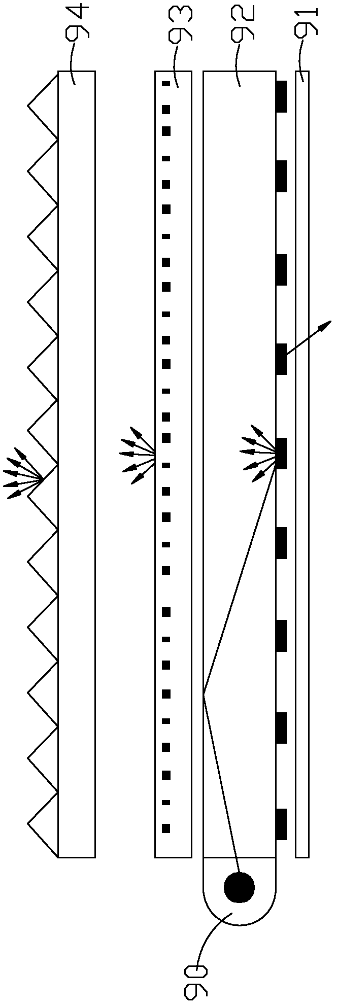
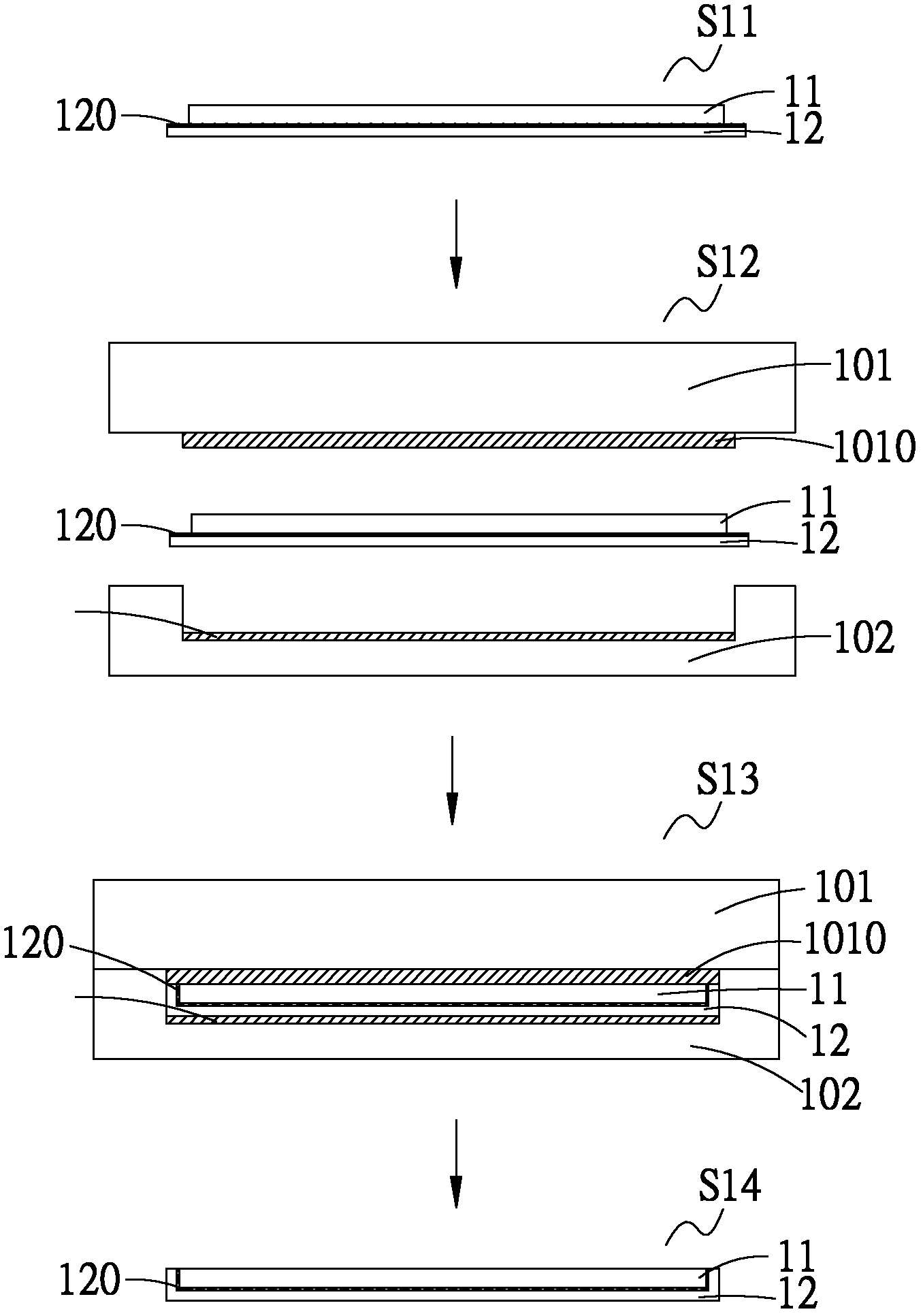
[0053] see Figure 5 , which is a schematic diagram of the second embodiment of the thermoforming method of the present invention. As shown in the figure, the thermocompression forming method of the present invention is suitable for manufacturing plate components. The plate components include a first plate 21 and a second plate 22. In this embodiment, the first plate 21 is preferably a light guide plate, which can The light guide plate is made of thermoplastic material, and the second plate 22 is preferably a reflective sheet, which can be made of thermoplastic material. The material for making the first sheet 21 can be polymethylmethacrylate (Polymethylmethacrylate, PMMA), cycloolefin polymer (Cycio Olefins Polymer, COP) or polycarbonate (Polycarbonate, PC) and other materials, all of which can be used to make the conductor Light board; the second...


PUM


Abstract

The present invention discloses a thermoforming method applicable for manufacturing a plate assembly having a first plate and a second plate. The thermoforming method comprises the steps of disposing the second plate on a lamination surface of the first plate; putting the first plate and the second plate into a first mold and a second mold respectively; heating and pressing the first mold and the second mold to deform any one of the lamination surfaces of the first plate and the second plate in order to laminate the first plate and the second plate; and opening the first mold and the second mold to remove the plate assembly. The first plate can be a light guide plate, and the second plate can be a reflector.

Description

technical field [0001] The present invention relates to a thermocompression forming method and its plate component, in particular to a thermocompression forming method for improving the manufacturing process of a light guide plate laminating a reflection sheet and reducing the process and its plate component. Background technique [0002] In general, backlight modules such as figure 1 As shown, it is mainly composed of a tube light source 90 (Light Source), a reflector 91 (Reflector), a light guide plate 92 (Light Guide Plate), a diffusion sheet 93 (Diffusion Sheet) and a prism sheet 94 (Prism Sheet). Such as figure 2 As shown, the basic working principle of the backlight module is as follows: [0003] S1: Convert the lamp light source into a surface light source through the light guide plate. [0004] S2: Use the reflection sheet at the bottom of the light guide plate to reflect the light emitted from the light guide plate back to the inside of the light guide plate. ...

Claims


Application Information

Patent Timeline
Patent Type & Authority Applications(China)
IPC IPC(8): B32B37/06B32B37/10B32B27/00
CPCB32B37/12B29C67/0044G02B6/0038B32B3/04B32B27/00G02B6/0036B32B27/36G02B6/0055B32B2369/00B32B2367/00B32B27/08B32B2333/12B32B27/308B32B38/06B32B27/365G02B6/0065B32B37/06B32B27/325B32B37/10Y10T156/1039
Inventor 张学祖庄元立
Owner CHENMING MOLD IND CORP
Why Eureka
Try Eureka