Sheet separation apparatus and separation method, and sheet attaching apparatus and attaching method

A technology of peeling device and peeling sheet, which is applied in the fields of sheet peeling device and peeling and sheet sticking device and sticking, can solve the problems of complicated device structure, large-scale overall device, etc., achieve simple structure, improve bending rigidity, restrain The effect of constructing complexity

Active Publication Date: 2013-04-24
LINTEC CORP
View PDF6 Cites 13 Cited by
  • Summary
  • Abstract
  • Description
  • Claims
  • Application Information

AI Technical Summary

Problems solved by technology

[0005] However, in the peeling device described in Patent Document 1, since the direction of the two release sheets is switched in different directions, the release sheet is sent out in the left and right direction relative to the take-out direction, and then it is necessary to switch the direction of the release sheet several times. Therefore, there are disadvantages such as complicated structure of the device, enlargement of the whole device, or disadvantages such as the use of a raw material of a release sheet that is divided into two in the width direction in advance.

Method used


Image

  • Sheet separation apparatus and separation method, and sheet attaching apparatus and attaching method
  • Sheet separation apparatus and separation method, and sheet attaching apparatus and attaching method
  • Sheet separation apparatus and separation method, and sheet attaching apparatus and attaching method

Examples


no. 1 approach 〕

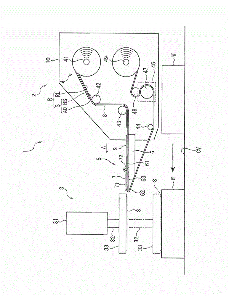
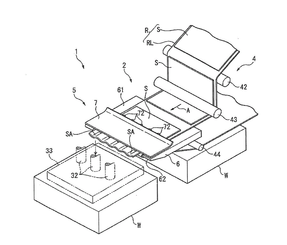
[0051] Such as figure 1 and figure 2 As shown, the sheet sticking device 1 of this embodiment peels the adhesive sheet S temporarily attached to one side of the strip-shaped release sheet RL from the release sheet RL, and sticks the peeled adhesive sheet S on the surface to be bonded. The device on the body W. Here, the adhesive sheet S is formed by laminating an adhesive layer AD on one side of the base sheet BS, and is prepared in advance as a raw material R temporarily bonded to one side of the release sheet RL with the adhesive layer AD interposed therebetween. prepare.

[0052] The sheet sticking device 1 includes a sheet peeling device 2 for peeling an adhesive sheet S from a release sheet RL of a raw material R, and a pressing unit 3 for pressing the peeled adhesive sheet S to an adherend W and sticking it thereto. The sheet peeling device 2 is provided with the take-out part 4 which takes out the raw material R, and the peeling part 5 which bends the peeling sheet ...

no. 2 approach 〕

[0067] Next, based on Figure 4 A second embodiment of the present invention will be described.

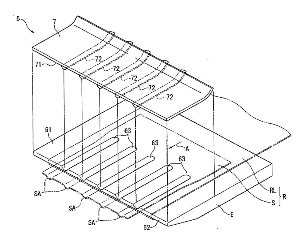
[0068] The peeling unit 5 in the sheet sticking apparatus 1A of this embodiment differs from the above-mentioned first embodiment only in that it includes a suction port 64 as a suction unit as a following unit in addition to the guide member 7 , and thus an overall view is omitted. In this sheet sticking apparatus 1A, by sucking the raw material R toward the peeling plate 6 side, a plurality of anti-bending regions SA in a concave-convex shape along the take-out direction A are formed on the adhesive sheet S.

[0069] Specifically, a plurality of suction ports 64 are provided in the groove portion 63 of the peeling plate 6 , and these suction ports 64 are connected to a suction device such as a decompression pump (not shown). In the sheet sticking device 1A provided with the peeling unit 5, the anti-folding area SA is also formed on the adhesive sheet S. Therefore, the bending r...

no. 3 approach 〕

[0071] Next, based on Figure 5 A third embodiment of the present invention will be described.

[0072] The peeling part 5 in the sheet|seat sticking apparatus 1B of this embodiment differs from the said 1st Embodiment in the point which provided the gas ejection part 8 other than the guide member 7 as a following part.

[0073] That is, the peeling unit 5 includes a peeling plate 6 and a gas ejection portion 8 facing the peeling plate 6 with the raw material R interposed therebetween. The gas ejection unit 8 includes a plurality of ejection ports (not shown) opened on the side of the adhesive sheet S, and ejects gas toward the raw material R. As shown in FIG.

[0074] In the above sheet sticking device 1B, the anti-folding area SA is formed on the adhesive sheet S by the gas ejection from the gas ejection unit 8, so that the adhesive sheet S can be reliably peeled off from the release sheet RL. . In this case, the adhesive sheet S is not in direct contact with the adhesive...


PUM


Abstract

A sheet separation apparatus (2) comprises: a feeding means (4) for feeding a raw fabric (R) in which an adhesive sheet (S) has been temporarily attached to a separation sheet (RL),and a separation means (5) for separating the adhesive sheet (S) from the separation sheet (RL). The separation means (5) comprises: a separation member (6) that has a bending end edge (62) for bending the separation sheet (RL),and a tracking means for forming a concave / convex-shaped transverse region (SA) at least in the adhesive sheet (S) in the feeding direction thereof. The separation member (6) comprises: a guide surface part (61) that continues to the bending end edge (62) and also guides the raw fabric (R),and a first concave / convex part (63) that is formed in the guide surface part (61) in the feeding direction of the raw fabric (R) and opens at the bending end edge (62). The tracking means comprises a guide member (7) provided with a second concave / convex part that fits together with the first concave / convex part (63) in a state where the raw fabric (R) is disposed between the separation member (6) and the second concave / convex part. The second concave / convex part comprises a convex part (72) that is provided extending to the bending end edge (62) in the feeding direction of the first concave / convex part.

Description

technical field [0001] The present invention relates to a sheet material peeling device and a peeling method, and a sheet material sticking device and sticking method. Background technique [0002] Conventionally, in a peeling device and a sticking device that takes out a raw material temporarily bonded with an adhesive sheet on one side of a tape-shaped release sheet, and peels the adhesive sheet from the release sheet of the taken-out raw material, it is known that When the temporary adhesive strength of the release sheet is strong, the technique of reliably peeling the adhesive sheet from the release sheet (for example, refer to Patent Document 1). [0003] The peeling device described in Patent Document 1 is a peeling device for peeling an adhesive sheet temporarily adhered to a peeling sheet that has been divided into two in the width direction in advance from the peeling sheet. The edge is bent obliquely, and the direction is changed laterally with respect to the take...

Claims


Application Information

Patent Timeline
Patent Type & Authority Applications(China)
IPC IPC(8): B65C9/18B65C9/26B65H41/00
CPCB65C9/1884B65C9/1865B65H37/002B65H2301/5122B65C9/0006B32B43/006B65H2701/194Y10T156/1195Y10T156/1978Y10T156/1944B65C9/18B65C9/26B65H41/00
Inventor 藤田敏弘
Owner LINTEC CORP
Why Eureka
Try Eureka