
Low-noise switching mode power supply transformer and low-noise switching power supply

A low-noise switching, switching power supply technology, applied in the direction of transformer/inductor coil/winding/connection, electrical components, output power conversion device, etc. and other problems to achieve the effect of suppressing common mode interference

Active Publication Date: 2013-04-24
锐立平芯微电子(广州)有限责任公司
View PDF4 Cites 7 Cited by
  • Summary
  • Abstract
  • Description
  • Claims
  • Application Information

AI Technical Summary

Problems solved by technology

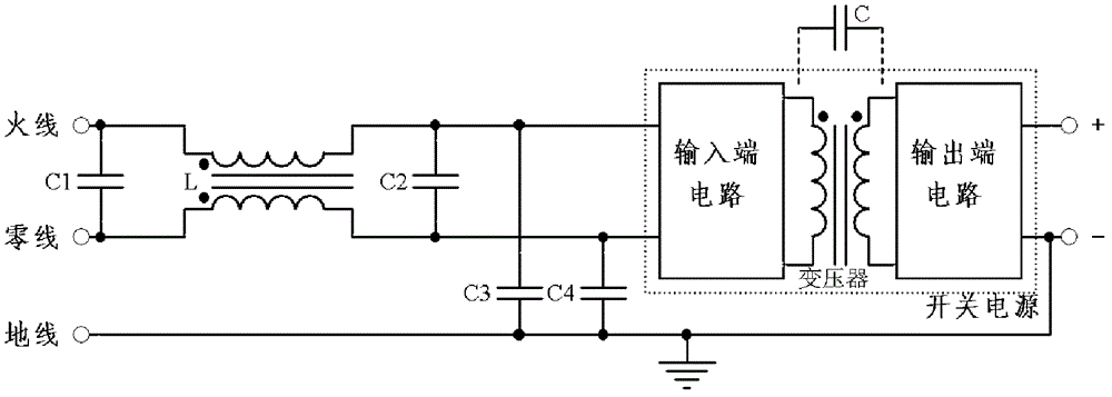
[0006]1. If it is not reliably grounded, due to the existence of the Y capacitor, the negative output terminal of the switching power supply and the entire shell will have half the voltage of the power supply voltage to the ground, which will easily cause personnel Electric shock, electricity leakage threatens the safety of precision devices, and produces power frequency interference to the signal detected by the sensor
[0007]2. One end of the output must be grounded, and it cannot be used in designs that require different power supplies.
However, if the coupling capacitance C is only reduced by keeping the primary winding away from the secondary winding, then the leakage inductance of the transformer will increase, affecting its conversion efficiency

Method used


Image

  • Low-noise switching mode power supply transformer and low-noise switching power supply
  • Low-noise switching mode power supply transformer and low-noise switching power supply
  • Low-noise switching mode power supply transformer and low-noise switching power supply

Examples


Embodiment 1

[0024] see Figure 4 , The half-bridge switching power supply includes a transformer, half-bridge drive tubes Q1, Q2, diodes D1, D2 and capacitor C. The primary and secondary windings each have two symmetrical windings with opposite ends. The A terminal of the primary winding is connected between the half-bridge drive tubes Q1 and Q2, the a terminal is connected to the b terminal and then grounded through the capacitor C; the B terminal of the primary winding is suspended, and the b terminal is connected to the a terminal; one end of the secondary winding is connected, The other end is two opposite ends, one of which is connected to the diode D1, and the other is connected to the diode D2. Diodes D1 and D2 are used for full wave rectification. At this time, the a-end and b-end of the primary winding are AC grounded through the capacitor C, and there is no high-frequency common-mode voltage to the earth; the high-frequency common-mode voltage distribution from A-end to a-end ...

Embodiment 2

[0026] see Figure 5 , The push-pull switching power supply includes a transformer, push-pull drive tubes Q1, Q2, diodes D1, D2. The primary and secondary windings each have two symmetrical windings with opposite ends. The push-pull drive tubes Q1 and Q2 are turned on in turn. Terminal A of the primary winding is connected to push-pull drive tube Q2, terminal B is connected to push-pull drive tube Q1, and terminals a and b are connected to a DC power supply VCC. One end of the secondary winding is connected, and the other end is two opposite ends, wherein one opposite end is connected to the diode D1, and the other end is connected to the diode D2. Diodes D1 and D2 are used for full wave rectification. At this time, the a-terminal and b-terminal of the primary winding are connected to VCC, and there is no high-frequency common-mode voltage to the ground; the high-frequency common-mode voltage distribution generated at any position from A-terminal to a-terminal, B-terminal t...


PUM


Abstract

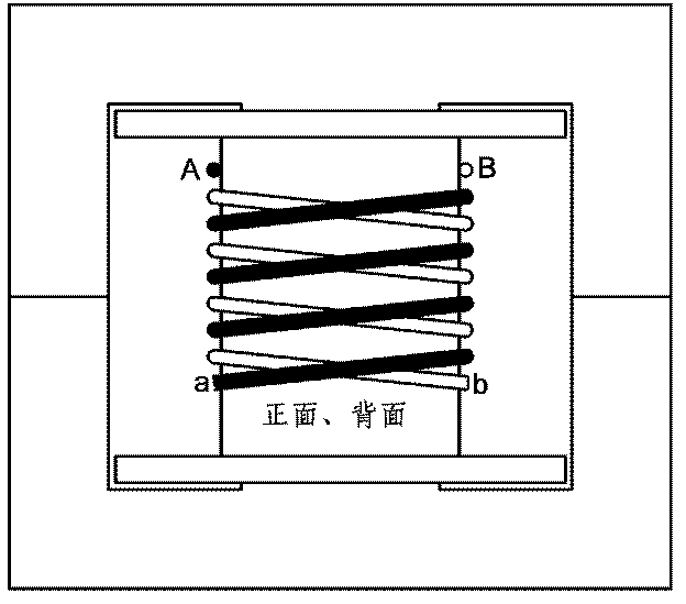
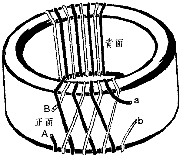
The invention discloses a low-noise switching mode power supply transformer. A primary winding and a secondary winding of the low-noise switching mode power supply transformer are symmetrical windings which are formed by a pair of coils with equal number of windings. The winding direction of the dotted terminal of each pair of coils is opposite. In addition, the invention discloses a low-noise switching power supply. The low-noise switching power supply comprises the disclosed transformer. Electric fields produced by high frequency alternating voltage distribution which is produced by the primary winding and the secondary winding of the transformer are cancelled out instead of reaching a secondary coil through capacity coupling between the primary level and secondary level. Therefore, common mode interference is restrained.

Description

Technical field [0001] The invention involves the field of switching power supply technology, which specially involves a low -noise switching power transformer and low noise switch power supply. Background technique [0002] The switching power supply is high, small, and high -power low noise switch power supply is widely used on the semiconductor manufacturing industry line, but compared with linear power supply, the electromagnetic interference of the switching power supply is more serious.Electromagnetic interference can not only cause pollution to the power supply line, but also interfere with the load or other electrical equipment. Therefore, the electromagnetic compatibility design is an important part of the design of the switching power supply.Among the microelectronics process equipment, there are both high -power mechanical and electrical components, as well as sensitive sensitivity devices and precision control devices. In order to prevent interference from the power s...

Claims


Application Information

Patent Timeline
IPC IPC(8): H01F27/28H02M1/12H02M7/162
Inventor 赵章琰李勇滔李英杰秦威夏洋
Owner 锐立平芯微电子(广州)有限责任公司
Learn More