
Inverter common-mode interference suppression circuit

A common-mode interference and suppression circuit technology, which is applied in the field of power conversion, can solve problems such as common-mode leakage current, affect the electromagnetic compatibility performance of the inverter, and common-mode interference, so as to achieve low cost, improve performance, and reduce EMI Effect

Inactive Publication Date: 2013-09-18
FONRICH NEW ENERGY TECH LTD
View PDF3 Cites 3 Cited by
  • Summary
  • Abstract
  • Description
  • Claims
  • Application Information

AI Technical Summary

Problems solved by technology

However, since the input and output sides of the inverter without a transformer are not isolated, common-mode leakage currents are prone to occur between the two sides.
Although there are some inverter topologies that do not have common-mode interference output in principle, because the components in reality are not ideal, they cannot fully realize the inverter switching time, voltage and current control, etc., so these topologies are also There are varying degrees of common-mode interference problems
The existence of common mode interference not only affects the electromagnetic compatibility performance of the inverter, but also brings safety problems

Method used


Image

  • Inverter common-mode interference suppression circuit
  • Inverter common-mode interference suppression circuit
  • Inverter common-mode interference suppression circuit

Examples


Embodiment Construction

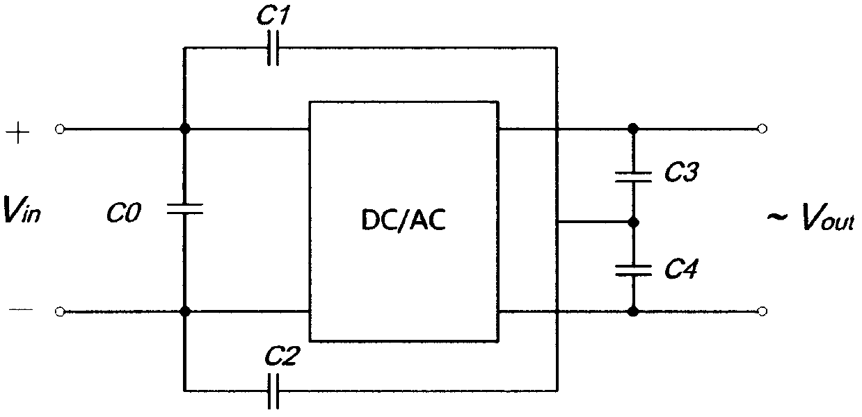
[0012] figure 1 , figure 2 , image 3 , Figure 4 , Figure 5 are a few examples of inverters using the invention. The two midpoint capacitors on the AC output side in these examples have the same capacitance. When the system is working, such as the inverter circuit (DC / AC module in the figure), under ideal conditions, there is no common-mode interference output, and the midpoint of the two midpoint capacitors maintains a constant voltage on the DC input side, that is, the common mode The voltage on the capacitor is constant; if the inverter circuit is not ideal, the inverter circuit will have a common-mode interference output. At this time, the common-mode capacitor provides a channel with a small impedance for the common-mode interference output, so the external output of the common-mode interference will change. Small; when the common-mode reactor (Z2 and Z3 in the figure) is added inside the loop of the midpoint capacitor, common-mode capacitor and inverter circuit, ...


PUM


Abstract

The invention relates to an inverter common-mode interference suppression circuit, which belongs to a circuit for suppressing the common-mode interference output between the direct current and alternating current sides of an inverter. The circuit can be widely applied to the inverter with high suppression requirements on common-mode current, such as transformer-free photovoltaic grid connected inverters. A realization method of the inverter common-mode interference suppression circuit is characterized in that two capacitors with the same capacity are connected in series between two electrodes of the alternating current output side, capacitors are connected between the direct current input end and the middle point of the capacitors, and in addition, a common-mode reactor is added in a proper position of the circuit. The inverter common-mode interference suppression circuit has the advantages that the suppression on the inverter circuit common-mode interference is realized at lower cost, the electromagnetic capacitive character of a system is improved, and in addition, the support is provided for realizing isolation-transformer-free inverters.

Description

technical field [0001] The invention belongs to the field of power conversion, and is a circuit for suppressing the output of common-mode interference between the DC and AC sides of the inverter, and can be widely used in inverters with high requirements for common-mode current suppression, such as transformerless photovoltaics Grid-connected inverters, etc. Background technique [0002] Inverters in many applications, such as photovoltaic grid-connected inverters, used to use isolated inverters with transformers. However, the existence of isolation transformers reduces system efficiency and increases costs. In order to overcome the deficiencies of the above-mentioned transformer-isolated inverters, the current trend is to use non-isolated inverters without transformers. The outstanding advantages of transformerless inverters are high efficiency and low overall cost. However, since the input and output sides of the inverter without a transformer are not isolated, common-mo...

Claims


Application Information

Patent Timeline
Patent Type & Authority Applications(China)
IPC IPC(8): H02M1/44
Inventor 张永
Owner FONRICH NEW ENERGY TECH LTD
Learn More