Super-resolution microscopic method and device based on fluorescence lifetime difference

A fluorescence lifetime and super-resolution technology, used in fluorescence/phosphorescence, material excitation analysis, etc., can solve the problems of reducing the system signal-to-noise ratio, adverse effects of the resolution ability, and reducing the fluorescence signal intensity, and achieve high system signal-to-noise ratio, structure, etc. Simple, small system changes

Inactive Publication Date: 2013-04-17
ZHEJIANG UNIV
View PDF3 Cites 13 Cited by
  • Summary
  • Abstract
  • Description
  • Claims
  • Application Information

AI Technical Summary

Problems solved by technology

However, this method reduces the intensity of the fluorescent signal that can be effectively used, reduces the signal-to-noise ratio of the system, and easily has an adverse effect on the actual resolution capability of the system.

Method used


Image

  • Super-resolution microscopic method and device based on fluorescence lifetime difference
  • Super-resolution microscopic method and device based on fluorescence lifetime difference
  • Super-resolution microscopic method and device based on fluorescence lifetime difference

Examples


Embodiment Construction

[0058] The present invention will be described in detail below in conjunction with the accompanying drawings and embodiments, but the present invention is not limited thereto.

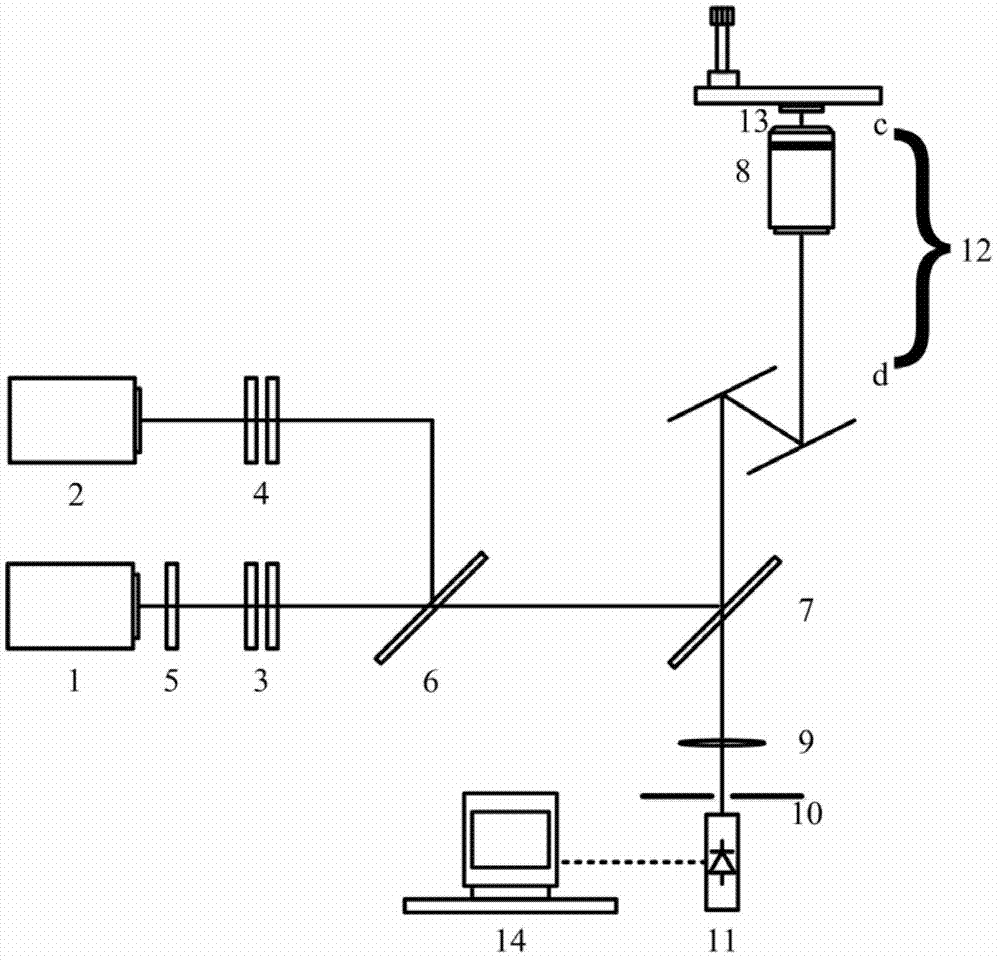
[0059] like figure 1 As shown, a super-resolution microscopy device based on fluorescence lifetime difference, including:

[0060] First laser 1, second laser 2, first polarization state converter 3, second polarization state converter 4, phase encoder 5, first dichroic mirror 6, second dichroic mirror 7, large numerical aperture microscope Objective lens 8, convex lens 9, pinhole 10, photoelectric sensor 11, scanner 12, fluorescent sample 13, computer 14. The pinhole 10 and the photoelectric sensing device 11 are in conjugate positions with the fluorescent sample 13 .

[0061] All the optical elements and fluorescent samples mentioned above include the first laser 1, the second laser 2, the first polarization state converter 3, the second polarization state converter 4, the phase encoder 2, the firs...


PUM

PropertyMeasurementUnit
refractive indexaaaaaaaaaa

Abstract

The invention discloses a super-resolution microscopic method based on fluorescence lifetime difference. The super-resolution microscopic method comprises the following steps: (1) focusing an excitation beam and a suppressed beam by a large numerical aperture microscope objective and scanning a fluorescence sample is scanned simultaneously by taking circularly polarized light as the excitation beam and taking the circularly polarized light coded by vortex phase as the suppressed beam; (2) collecting fluorescence emitted by the fluorescence sample by utilizing the large numerical aperture microscope objective and obtaining a view picture of fluorescence intensity image by a photoelectric sensing device; (3) obtaining corresponding fluorescence lifetime information by analyzing the fluorescence intensity information of the fluorescence intensity image; (4) setting a time gate for separating a long-life fluorescence image and a short-life fluorescence image from the fluorescence intensity information; and (5) setting a weight and subtracting the weighted long-life fluorescence image from the short-life fluorescence image to obtain a final super-resolution microscopic image. The invention also discloses a super-resolution microscopic device based on the fluorescence lifetime difference.

Description

technical field [0001] The invention relates to the field of microscopic imaging, in particular to a super-resolution microscopic method and device based on fluorescence lifetime difference. Background technique [0002] Like most optical imaging, the Abbe diffraction limit has restricted the improvement of the resolution of the microscope system since the invention of the microscope. Early microscope systems were all wide-field imaging systems with limited imaging resolution. This situation was not improved to some extent until the invention of the confocal microscope system (Confocal Microscope). The basic concept of confocal microscopy was proposed by M.Minsky et al. in 1957 (see M.Minsky et al. Microscopy Apparatus, US Patent 3013467), but the technique was not really instrumented until 1978 (see C. Cremer et al. Considerations on a laser-scanning-microscope with high resolution and depth of field, Microscopia Acta 81, 31-44 (1978)). Compared with the traditional wide...

Claims


Application Information

Patent Timeline
Patent Type & Authority Applications(China)
IPC IPC(8): G01N21/64
Inventor 匡翠方郝翔李帅顾兆泰王轶凡
Owner ZHEJIANG UNIV
Why Eureka
Try Eureka