
Testing device and method for three-dimensional PIV (Particle Image Velocimetry) internal flow field testing system of hydraulic retarder

A technology of hydraulic retarder and test system, which is applied in measurement devices, fluid dynamics tests, and testing of machine/structural components, etc. It can solve the limitations of CFD analysis, and can not maturely apply hydraulic component parameter optimization and numerical simulation models. Insufficient and other problems, to achieve the effect of optimized design and clear and accurate images

Inactive Publication Date: 2013-04-17
ZHEJIANG UNIV
View PDF3 Cites 40 Cited by
  • Summary
  • Abstract
  • Description
  • Claims
  • Application Information

AI Technical Summary

Problems solved by technology

However, the current flow field analysis using CFD is carried out under many simplified conditions. The steady-state assumptions made only reflect the static characteristics of the components, and the numerical simulation model is not complete enough. CFD analysis is still limited to positive verification. Numerical simulation has not been maturely applied to the optimization of hydraulic component parameters

Method used


Image

  • Testing device and method for three-dimensional PIV (Particle Image Velocimetry) internal flow field testing system of hydraulic retarder
  • Testing device and method for three-dimensional PIV (Particle Image Velocimetry) internal flow field testing system of hydraulic retarder
  • Testing device and method for three-dimensional PIV (Particle Image Velocimetry) internal flow field testing system of hydraulic retarder

Examples


Embodiment Construction

[0020] The present invention will be further described below in conjunction with the accompanying drawings and embodiments.

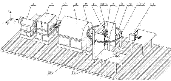
[0021] The present invention adopts Particle Image Velocimetry (PIV for short) to test the three-dimensional flow field of the visualized hydraulic retarder, so as to obtain the velocity distribution of the internal flow field. The internal flow field of the hydraulic retarder is very complex and in a highly turbulent state. PIV technology does not interfere with the flow field, and can obtain the instantaneous velocity field of the internal flow field for quantitative measurement of the entire field. Therefore, the research on the fine structure and mechanism of the flow It is of great significance and is a state-of-the-art technology for measuring complex flow fields. The internal flow field of the hydraulic retarder is studied by PIV shooting, and the results can be used for the design and optimization of the internal hydraulic components of the reta...


PUM


Abstract

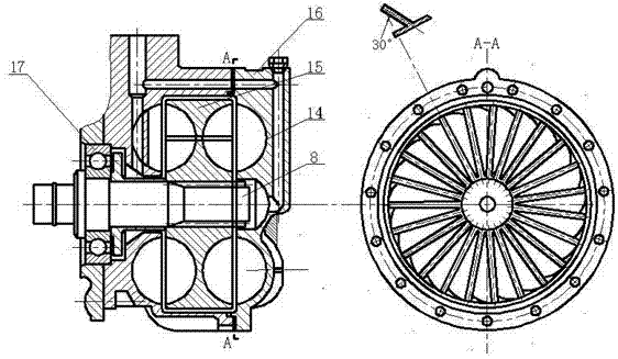
The invention discloses a testing device and a testing method for a three-dimensional PIV (Particle Image Velocimetry) internal flow field testing system of a hydraulic retarder. The testing device comprises a driving motor, a transmission case, a pneumatic clutch, a flywheel case, a torsion and rotating speed sensor, a braking shaft, a visualized hydraulic retarder, a visualized testing chamber, a circular guide rail, a synchronizer, a double-pulse laser, CCD (Charge Coupled Device) cameras, a water storage tank, a water pump, a pressure inductor, a pressure reducer, a particle dispenser, an electromagnetic flowmeter and the like; the visualized testing chamber is made of a transparent material and is suitable for an aqueous medium; the braking shaft is driven by an external driving system, is supported by a bearing, passes through a shell of the hydraulic retarder and is connected with a driving wheel of the retarder; the first CCD camera is arranged at the top of the visualized testing chamber and is used for shooting downwards; the second CCD camera and the double-pulse laser are arranged on the circular guide rail and can arbitrarily rotate along the guide rail; and the circular guide rail and the visualized testing chamber are respectively fixed on the base. The testing device and the method disclosed by the invention can be used for carrying out three-dimensional PIV measurement on the internal flow field of the hydraulic retarder and is simple and compact in structure, good in universality and easy to control.

Description

technical field [0001] The invention relates to a test device and method for a three-dimensional PIV test system of a flow field in a hydraulic reducer. Background technique [0002] As an auxiliary braking device, the hydraulic retarder has been applied to large and medium-sized vehicles. The hydraulic reducer is mainly composed of housing, heat exchanger, stator impeller, mover impeller, spline shaft, controller and other components. The device drives the hydraulic rotation through the mover and impacts the stator. At this time, the stator will also generate a reaction force on the mover through the hydraulic force, thereby hindering the rotation of the rotor and realizing non-contact braking. It is a high-end retarder product. [0003] The internal flow field of the hydraulic retarder is a complex three-dimensional flow. Since the three-dimensional flow theory is not yet mature, it cannot be used to accurately calculate and analyze the internal flow field of the hydrauli...

Claims


Application Information

Patent Timeline
Patent Type & Authority Applications(China)
IPC IPC(8): G01M10/00
Inventor 周晓军冯玮魏燕定罗竹辉
Owner ZHEJIANG UNIV
Learn More