
Double differential pressure moisture flow measuring device based on long-throat-neck venturi

A measuring device, Venturi technology, applied in the direction of volume/mass flow generated by mechanical effects, fluid flow detected by measuring pressure difference, etc., can solve the problem of low signal-to-noise ratio of measurement signal, low signal-to-noise ratio of pressure measurement signal, and affecting the system Discrimination ability and other problems, to achieve the effect of low signal-to-noise ratio of the measurement signal, optimize the expansion angle, and lengthen the length of the throat

Active Publication Date: 2013-04-17
TIANJIN UNIV +1
View PDF4 Cites 16 Cited by
  • Summary
  • Abstract
  • Description
  • Claims
  • Application Information

AI Technical Summary

Problems solved by technology

Practice has proved that this design has the following disadvantages: (1) As one of the detection elements, the conical core can contribute a differential pressure measurement information, but when ensuring the difference between the two throttling devices and satisfying the common cross-measurement range, there will be This means that the measurement capability of the device is limited, the range ratio is less than one-third, and its use is limited under the conditions of large flow rate changes in industrial sites; (2) The patented device uses two kinds of throttling The component is used for moisture measurement, which is complex and costly; (3) The conical core of the patented device and the installation method of the pipeline adopt a welding process, and the coaxiality of the two is difficult to guarantee, so that the measuring device with the same structural design The processing inconsistency is obvious, resulting in a large workload for device calibration; (4) The Venturi throat of the patented device is designed according to the standard Venturi, and in-depth research shows that the acceleration distance of the liquid phase is insufficient when passing through the throat, resulting in insufficient mixing of the gas-liquid two-phase (5) The design of the expansion angle of the Venturi expansion section of the patented device is not ideal, which makes the downstream expansion section easy to cause backflow and form effusion, which ultimately affects the system's ability to respond to higher liquid phase holdups. Identification ability; (6) The pressure taking method in this patented device is single-point pressure taking, and an external independent small gas-liquid isolation tank is used to realize gas-liquid isolation and pressure taking, the signal-to-noise ratio of the measurement signal is low, and the efficiency of gas-liquid isolation is low ; (7) All the blowdown valves in the patented device are located at the lower end of the gas-liquid isolation tank, and its existing design cannot realize the overall synchronous sewage discharge of the isolation tank and the main measuring pipeline; (8) All the gas-liquid isolation tanks in the patented device are located in the metering pipe One side affects the weight balance of the overall device. After installation, due to the existence of rotating torque, it affects the safety and service life of the device.
Practice has proved that the experimental device has the following disadvantages: (1) Each pressure-taking position adopts a direct pressure-taking method on the pipe wall, and there is only one pressure-taking point. As a result, the external independent gas-liquid isolation tank has low gas-liquid isolation efficiency, low signal-to-noise ratio of pressure measurement signals, and unsatisfactory repeatability; (2) The length of the throat is insufficient, only 2.8 times the inner diameter of the throat (3) The throat is taken The pressure position is not ideal. This article only takes pressure at the upstream and downstream of the throat, and the pressure position is not the best position; (4) The expansion angle of the expansion section is not ideal. The downstream differential pressure signal is meaningless and unusable, so the applicability of the final model is limited

Method used


Image

  • Double differential pressure moisture flow measuring device based on long-throat-neck venturi
  • Double differential pressure moisture flow measuring device based on long-throat-neck venturi
  • Double differential pressure moisture flow measuring device based on long-throat-neck venturi

Examples


Embodiment Construction

[0013] The present invention will be described in further detail below with reference to the accompanying drawings.

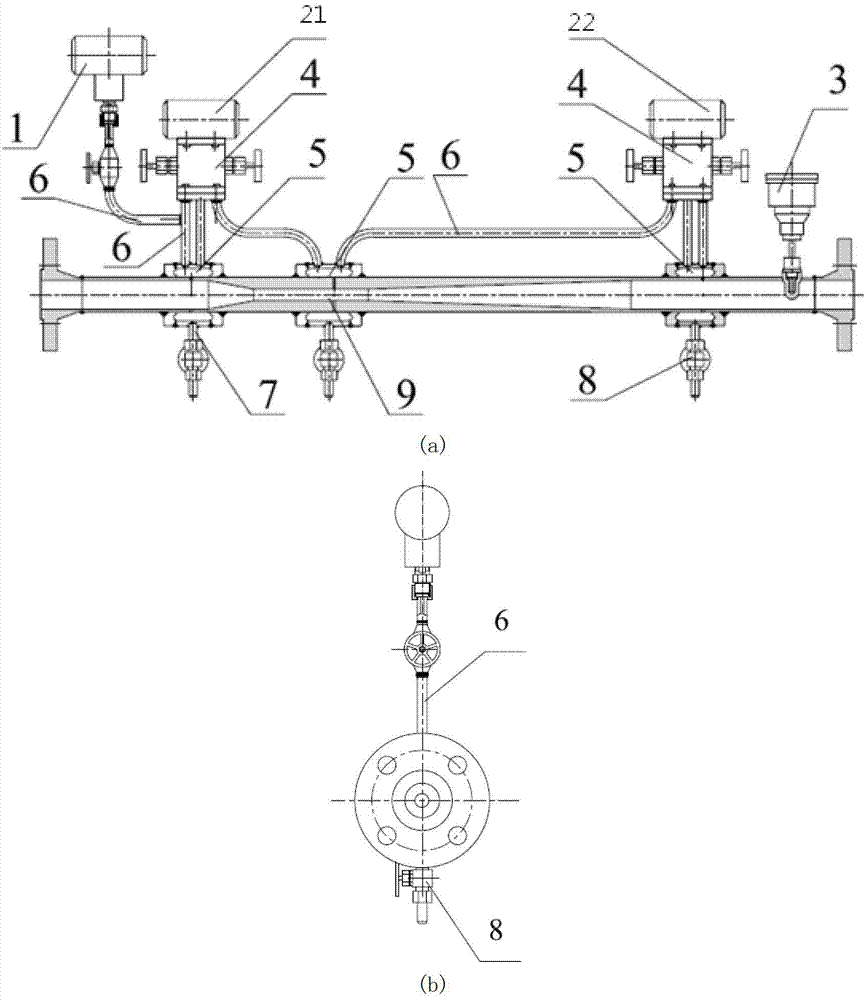
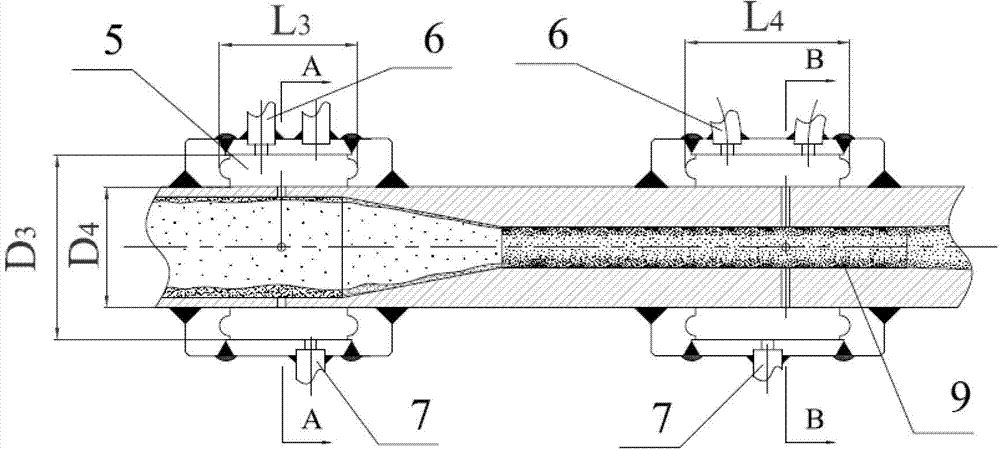
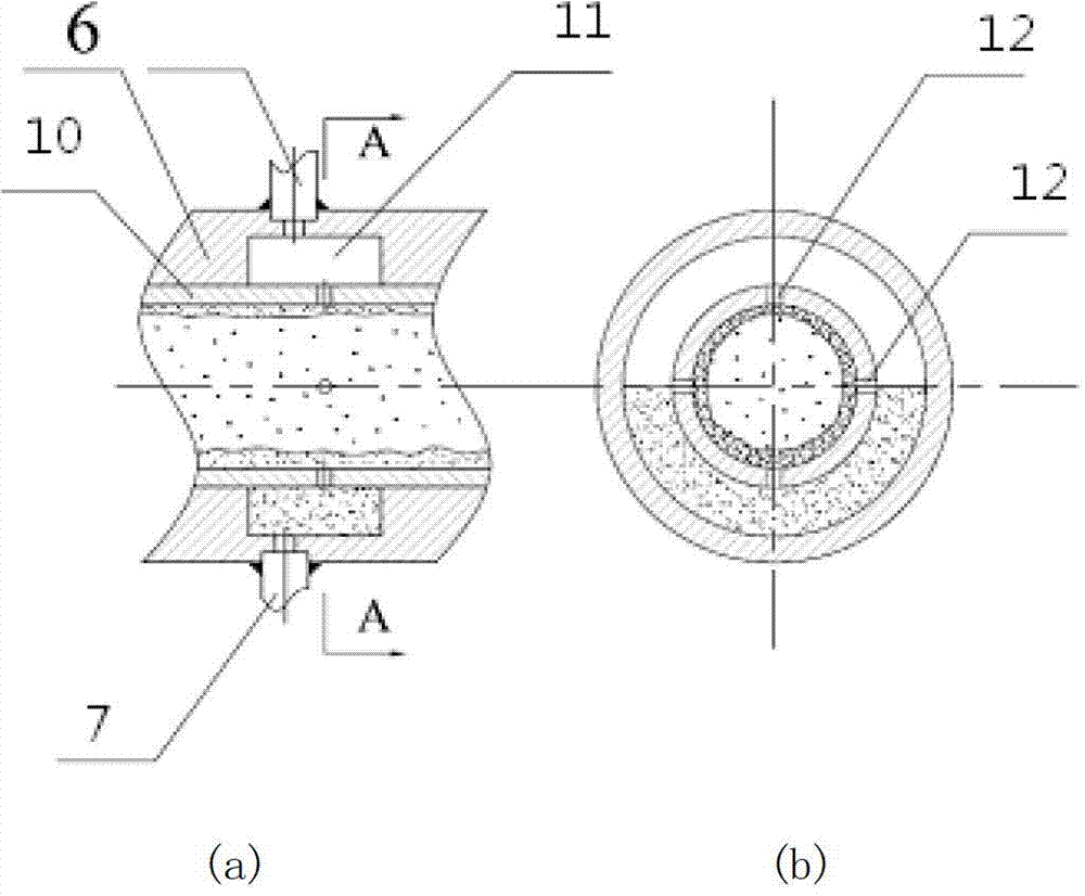
[0014] The invention is a double differential pressure wet gas flow measuring device based on a long throat Venturi. The present invention is different from the previous wet gas flow measuring device in that it adopts an annular chamber gas-liquid isolation pressure taker as the pressure takeover mechanism on the basis of the optimally designed Venturi structure.

[0015] The two transmitters share an annular gas-liquid isolation pressure taker at the throat. A pressure transmitter is installed at the upstream inlet, and the pressure introduction pipe of the transmitter can be bypassed by the upstream pressure introduction pipe of the first differential pressure transmitter. The temperature transmitter is fixed downstream of the device for measuring temperature.

[0016] like figure 1 As shown, the device of the present invention, the measuring pipeline is a...


PUM


Abstract

The invention belongs to technical field of gas-liquid two-phase flow measurement of wet gas and relates to a double differential pressure moisture flow measuring device based on a long-throat-neck venturi. The double differential pressure moisture flow measuring device comprises a venturi measuring pipeline, a first differential pressure transmitter and a second differential pressure transmitter. A pressure taking position is respectively arranged at the upstream of the venturi measuring pipeline and the mid downstream and the downstream position of the throat, four inner pressure taking holes are arranged on the pipe wall of an identical plane perpendicular to the axis of each pressure taking position, and an annular chamber structure is fixed on the periphery of the four inner pressure taking holes. The first differential pressure transmitter is respectively connected with an external pressure introduction pipe connected with the two pressure taking positions at the upstream and the mid downstream of the throat, and the second differential pressure transmitter is respectively connected with an external pressure introduction pipe connected with the pressure taking position at the mid downstream of the throat and the pressure taking position at the downstream. The measuring device has the advantages of being simple in structure, free of movable parts, reliable in measurement, high in accuracy and simple and convenient to implement.

Description

technical field [0001] The invention belongs to the technical field of moisture gas-liquid two-phase flow measurement, and relates to a double differential pressure wet gas flow measurement device based on a long-throat venturi. Background technique [0002] Moisture, as a special form of gas-liquid two-phase flow, exists widely in nature and industry. When gas or liquid flows alone, the flow laws are basically the same, and they all obey the fluid continuity equation and Bernoulli equation, and the mathematical models are basically similar. When they co-exist and flow at the same time, due to the large difference in the medium properties of the two-phase fluid, such as the friction coefficient, fluid density and viscosity and other physical parameters are different, coupled with the influence of working pressure and two-phase speed slip , making gas-liquid two-phase flow more complex than single-phase flow, and many criterion relations and analysis methods in single-phase ...

Claims


Application Information

Patent Timeline
IPC IPC(8): G01F1/34
Inventor 徐英张涛张强巴玺丽白晓东杨莉娜韩方勇孙铁民王春燕王钦赵钰
Owner TIANJIN UNIV
Learn More