Automatic edge cutting method for plant fiber molding product and automatic edge cutting machine
A molding product and plant fiber technology, applied in the field of automatic edge trimming equipment, can solve problems such as large horizontal impact force, limitation of up and down movement stroke, and no edge trimming of products
- Summary
- Abstract
- Description
- Claims
- Application Information
AI Technical Summary
Problems solved by technology
Method used
Image
Examples
Embodiment 1
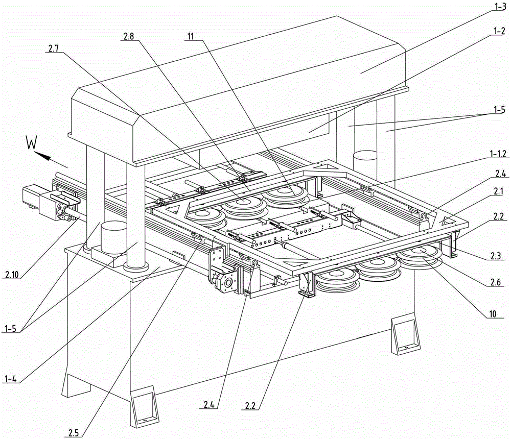
[0077] Such as image 3 , Figure 4 , Figure 5 , Figure 12-1 , Figure 13 The automatic edge trimming machine for plant fiber molded products shown includes: an edge trimming and clamping mechanism, a product transfer mechanism, and a waste edge removal mechanism. The trimming and clamping mechanism mainly includes an upper trimming mold; an upper mounting plate, a lower trimming mold, a lower mounting plate, and a power mechanism. The power mechanism directly or indirectly drives the upper mounting plate to move relative to the lower mounting plate. The trimming and clamping mechanism can have various forms, such as: three-plate type trimming and clamping mechanism ( Figure 11 shown) and two-plate type trimming and clamping mechanism ( Figure 9 shown).
[0078] The two-plate type trimming and mold clamping mechanism includes: upper trimming mold, upper mounting plate, lower trimming mold, lower mounting plate, clamping rod, drive (including direct drive or indirect...
Embodiment 2
[0108] Such as Figure 15 , Figure 16 As shown, in the automatic trimming machine for plant fiber molded products described in this embodiment, the specific structure of its product transfer mechanism can also be a rod-type product transfer mechanism.
[0109] The transport frame in Embodiment 1 is a transport bar 15 in this embodiment, and the transport bar is not a frame structure but a bar, which can also be called a bar type transport frame. Root bar is called delivery bar, and the disk opening of front row suction cup group 2.6 is fixed on the front fixed plate 2.3 downwards, and the disk mouth of rear row suction cup group 2.7 is fixed on the rear fixed plate 2.8 downwards, and one end of the front fixed plate and the rear One end of the fixed plate is installed on the conveying rod at a certain interval, and generally there is a space greater than the contour of the upper trimming mold between the front and back two rows of suction cup groups. The two ends of the del...
PUM
 Abstract
Description
Claims
Application Information
 - R&D
- Intellectual Property
- Life Sciences
- Materials
- Tech Scout
- Unparalleled Data Quality
- Higher Quality Content
- 60% Fewer Hallucinations
Browse by: Latest US Patents, China's latest patents, Technical Efficacy Thesaurus, Application Domain, Technology Topic, Popular Technical Reports.
© 2025 PatSnap. All rights reserved.Legal|Privacy policy|Modern Slavery Act Transparency Statement|Sitemap|About US| Contact US: help@patsnap.com


