
Friction stir welding fixture in mechanical trigger control mode and method for controlling friction stir welding fixture

A technology of friction stir welding and trigger control, which is applied in the direction of manufacturing tools, welding equipment, welding equipment, etc., can solve problems such as press plate cylinder misoperation, photoelectric sensor interference, etc., and achieve the effect of eliminating misoperation, reducing cost, and automatically controlling operation

Active Publication Date: 2013-04-17
UNITED AUTOMOTIVE ELECTRONICS SYST
View PDF8 Cites 5 Cited by
  • Summary
  • Abstract
  • Description
  • Claims
  • Application Information

AI Technical Summary

Problems solved by technology

At present, the opening and closing of the pressure plate is mainly controlled by the pressure plate cylinder, and the pressure plate cylinder is controlled by a photoelectric sensor. When stirring welding, the welding head will produce strips of extruded materials, and these extruded materials will be photoelectric. The sensor causes interference, which in turn causes the malfunction of the platen cylinder

Method used


Image

  • Friction stir welding fixture in mechanical trigger control mode and method for controlling friction stir welding fixture
  • Friction stir welding fixture in mechanical trigger control mode and method for controlling friction stir welding fixture
  • Friction stir welding fixture in mechanical trigger control mode and method for controlling friction stir welding fixture

Examples


Embodiment Construction

[0026] The present invention will be further described in detail below in conjunction with the accompanying drawings and specific embodiments.

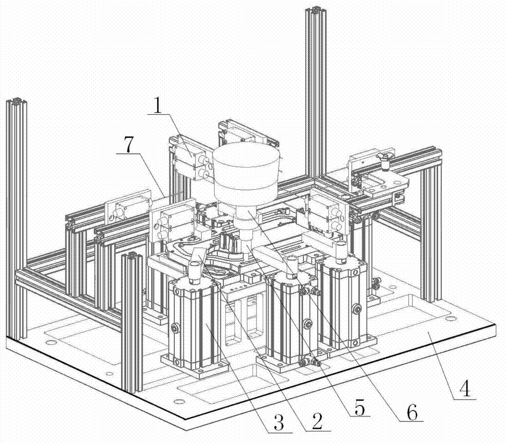
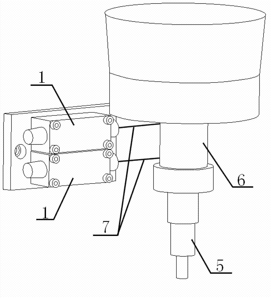
[0027] The mechanical trigger control mode fixture of the friction stir welding provided by the present invention, such as figure 2 As shown, it includes a fixture base 4, a control unit (PLC is used in this embodiment), a trigger element 6, a limit switch 1 and six press plates 2, each press plate 2 is connected with a press plate cylinder 3, and each press plate cylinder 3 It corresponds to at least one limit switch 1 and is controlled by the corresponding limit switch 1 . The limit switch 1 corresponding to each platen cylinder 3 is located in front of the platen 2 controlled by the platen cylinder 3 on the running track of the welding head 5 . In this embodiment, in order to improve the contact reliability between the trigger element 6 and the limit switch 1 and ensure the accuracy of the automatic control of the fixture, two li...


PUM


Abstract

The invention discloses a friction stir welding fixture in a mechanical trigger control mode and a method for controlling the friction stir welding fixture. The friction stir welding fixture comprises a fixture base, a control unit, a trigger element, limit switches and a plurality of pressure plates; each pressure plate is connected with a pressure plate cylinder, each pressure plate cylinder corresponds to at least one limit switch and is controlled by the corresponding limit switches, and the limit switches and the pressure plate cylinders are connected with the control unit; and the trigger element and the limit switches are matched with one another and are mounted on a friction stir welding head. The pressure plate cylinders are controlled by the mechanical trigger type limit switches and the trigger element, possibility of malfunction of the pressure plate cylinders is eliminated, the pressure plates are driven by the pressure plate cylinders to be automatically opened before the welding head moves to the pressure plates during movement, and are reset to press workpieces after the welding head passes the pressure plates, the integral fixture is automatically controlled and is reliable in running, and the cost is lowered.

Description

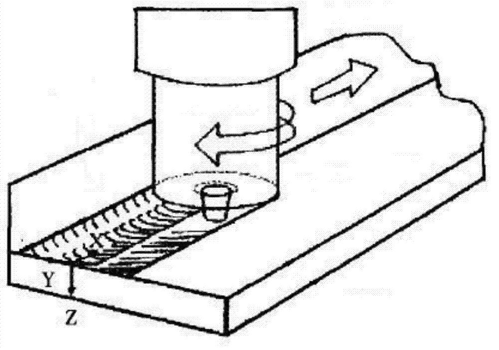
technical field [0001] The invention relates to a welding jig, and specifically belongs to a mechanical trigger control mode jig for friction stir welding, especially suitable for polygonal welds, closed curve welds or irregular shapes. Background technique [0002] Friction Stir Welding (FSW) was invented by the British Welding Institute (TWI) in 1991, which is an innovative solid-phase joining technology, which is derived from traditional friction welding and is more suitable for long and straight welds of welding. Compared with the traditional fusion welding method, friction stir welding has the advantages of fine weld grain, no smoke, no spatter, no porosity, no solder, no protective gas during welding, small stress and deformation of the workpiece after welding, etc., especially Suitable for aluminum alloy welding. [0003] Friction stir welding is a purely mechanized continuous solid-phase joining method, such as figure 1 As shown, during the welding process, a cyli...

Claims


Application Information

Patent Timeline
Patent Type & Authority Applications(China)
IPC IPC(8): B23K20/12B23K20/26B23K37/04
Inventor 王学全巩锦富黄宇冬张舜
Owner UNITED AUTOMOTIVE ELECTRONICS SYST
Learn More