
Method for solidifying protective clip in carbon/silicon carbide brake disc

A protection clip, silicon carbide technology, applied in the direction of brake parts, etc., can solve problems such as failure to meet the requirements of design drawings, damage to stressed parts, damage to steel clips and brake discs, etc., to avoid difficulties in riveting and reduce stress. Uniform and reliable connection

Inactive Publication Date: 2013-04-10
XIAN AVIATION BRAKE TECH
View PDF3 Cites 0 Cited by
  • Summary
  • Abstract
  • Description
  • Claims
  • Application Information

AI Technical Summary

Problems solved by technology

During the ceramicization process, the heat-treated brake disc will be deformed, and the deformation cannot be eliminated by machining, so that the assembly relationship and position between the steel clip and the brake disc cannot be guaranteed. It is difficult to rivet the disk, and it cannot meet the requirements of the design drawings after barely riveting
The brake disc is prone to vibration during the braking process, thereby damaging the steel clip and the brake disc; 2) Due to the large compression modulus and high rigidity of the carbon / silicon carbide brake disc, it is not easy to deform when it is impacted, resulting in excessive concentration of force. 3) The contact surface of the brake disc steel clip and the brake disc is too small, so that the force on the contact part of the brake disc and the steel clip is too concentrated, resulting in damage to the stressed part that cannot withstand the impact force

Method used


Image

  • Method for solidifying protective clip in carbon/silicon carbide brake disc
  • Method for solidifying protective clip in carbon/silicon carbide brake disc
  • Method for solidifying protective clip in carbon/silicon carbide brake disc

Examples


Embodiment 1

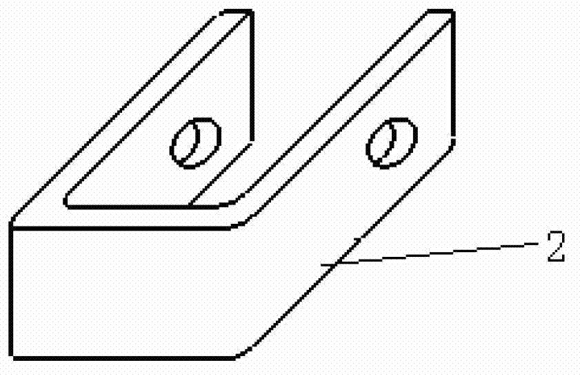
[0029] This example is a method of curing a protective clip in a carbon / silicon carbide brake rotor. The brake disc is a dynamic brake disc, that is, a dynamic disc. The structure of the protective clip is a common U-shaped structure made of carbon / silicon carbide.

[0030] This embodiment includes the following steps:

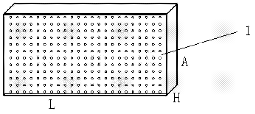
[0031] Step 1, making the tire mold of the protective clip. Described tire mold is made of graphite, is cuboid, and its external dimension is the same as the size of the U-shaped opening of the protective clip made, and its length is determined according to the quantity of required protective clips, and the width is the depth of the U-shaped opening of the protective clip. 3 times. The height b of the tire mold is equal to the thickness of the keyboard. There are through holes on the surface of the tire mold, and the distance between the centers of adjacent through holes is 5-10 mm; the diameter of the through holes is 3-5 mm. The chamfer of the long side...

Embodiment 2

[0042] This example is a method of curing a protective clip in a carbon / silicon carbide brake rotor. The brake disc is a carbon / carbon static brake disc, that is, a static disc. The structure of the protective clip is a common U-shaped structure made of carbon / silicon carbide.

[0043] This embodiment includes the following steps:

[0044] Step 1, making the tire mold of the protective clip. Described tire mold is made of graphite, is cuboid, and its external dimension is the same as the size of the U-shaped opening of the protective clip made, and its length is determined according to the quantity of required protective clips, and the width is the depth of the U-shaped opening of the protective clip. 3 times. The height b of the tire mold is equal to the thickness of the static disk key. There are through holes on the surface of the tire mold, and the distance between the centers of adjacent through holes is 5-10 mm; the diameter of the through holes is 3-5 mm. The chamf...

Embodiment 3

[0055] This example is a method of curing a protective clip in a carbon / silicon carbide brake rotor. The brake disc is a dynamic brake disc, that is, a dynamic disc. The structure of the protective clip is a common U-shaped structure made of carbon / silicon carbide.

[0056] This embodiment includes the following steps:

[0057] Step 1, making the tire mold of the protective clip. Described tire mold is made of graphite, is cuboid, and its external dimension is the same as the size of the U-shaped opening of the protective clip made, and its length is determined according to the quantity of required protective clips, and the width is the depth of the U-shaped opening of the protective clip. 3 times. The height b of the tire mold is equal to the thickness of the keyboard. There are through holes on the surface of the tire mold, and the distance between the centers of adjacent through holes is 5-10 mm; the diameter of the through holes is 3-5 mm. The chamfer of the long side...


PUM


Abstract

The invention relates to a method for solidifying a protective clip in a carbon / silicon carbide brake disc. The method comprises the following steps: based on the preparation of a carbon / silicon carbide protective clip, preparing a precasting body on a special fixture in a carbon cloth lamination winding mode; densifying the precasting body by adopting CVD (Chemical Vapor Deposition); when the density is increased to (1.60+ / -1) g / cm<3>, taking out the precasting body to be machined and taking out the fixture; connecting the obtained precasting body to a brake disc blank to be treated in a ceramic-casting mode by using a carbon rivet; carrying out a ceramic-casting treatment on the precasting body and the brake disc together so as to integrate the carbon / silicon carbide protective clip with the carbon ceramic brake disc; and carrying out machining treatment and anti-oxidation coating treatment, thereby forming the carbon / silicon carbide brake disc with the carbon / silicon carbide protective clip. According to the invention, the riveting difficulty caused by the deformation of the brake disc treated in the ceramic-casting mode is overcome; the carbon / silicon carbide protective clip cannot be damaged easily and has the characteristics of small density and abrasion resistance; and the load-carrying surface of the brake disc is enlarged by increasing the contact area of the carbon / silicon carbide protective clip, so that the damage on the brake disc due to the load-carrying unevenness of the brake disc is reduced. In addition, the protective clip provided by the invention also has the characteristics of reliability in connection, high temperature resistance, abrasion resistance, good toughness and convenience in assembling.

Description

technical field [0001] The invention relates to the field of carbon / silicon carbide brake discs for aircraft wheels, in particular to a method for curing protective clips in carbon / silicon carbide brake discs. Background technique [0002] The carbon / silicon carbide brake disc protection clip is a force transmission component, and its working conditions are very harsh. In addition to force transmission, it also requires reliable connection, impact resistance, high temperature resistance, and wear resistance. The main functions of the carbon / silicon carbide protection clip are: first, to transmit the torque to the drive key of the wheel through the carbon / silicon carbide protection clip; second, to make the torque evenly distributed on the carbon / silicon carbide brake disc, so that the The force on the keyway of the silicon brake disc will not be too concentrated to avoid damage to the keyway; the third is to prevent the wheel drive key from directly contacting the carbon / sil...

Claims


Application Information

Patent Timeline
IPC IPC(8): C04B35/80C04B35/565C04B35/622F16D65/02
Inventor 张正参田广来刘海平张琦张晓伟
Owner XIAN AVIATION BRAKE TECH
Learn More