Electrical appliance
A technology for electrical products and power cables, used in electrical components, circuit devices, wireless systems/telephones, etc., can solve problems such as inability to manage, and achieve the effect of preventing damage and falling off, and stabilizing wireless communication
- Summary
- Abstract
- Description
- Claims
- Application Information
AI Technical Summary
Problems solved by technology
Method used
Image

Examples
Embodiment 1
[0026] (Example 1, refer to Figure 1 ~ Figure 3 )
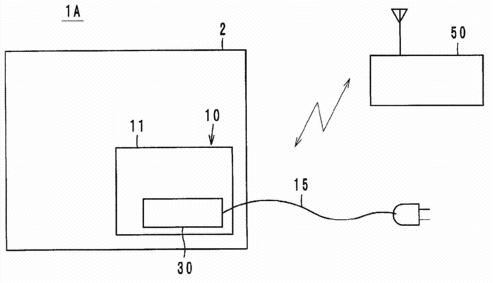
[0027] Such as figure 1 As shown, in the electrical product 1A of Embodiment 1, the wireless IC element 30 is mounted on the substrate 11 of the power supply unit 10 built in the product body 2 formed of metal or the like, and the wireless IC element 30 is connected to the At least a part of the external power cable 15 is coupled (directly or indirectly). Therefore, the power cable 15 functions as an antenna of the wireless IC device 30 and wirelessly communicates with the reader / writer 50 of the RFID system in a predetermined frequency band. In addition, the "coupling" mentioned in this specification means any one of direct electrical coupling, magnetic field coupling, electric field coupling, or electromagnetic field coupling.
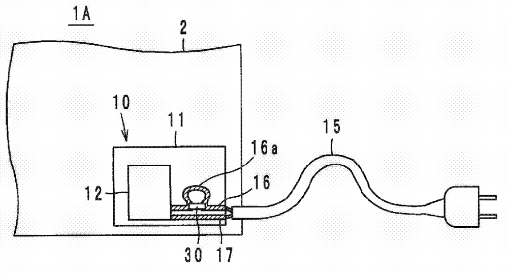
[0028] The details are as figure 2 As shown, conductor patterns 16 and 17 connected to a power cable 15 are formed on the power substrate 11 in addition to the power supply unit 12 . Such as ...
Embodiment 2
[0037] (Example 2, refer to Figure 6 and Figure 7 )
[0038] Such as Figure 6 As shown, in the electrical product 1B of Embodiment 2, the wireless IC element 30 is mounted on the power supply board 11, the wireless IC element 30 is coupled (directly or indirectly) to at least a part of the power supply cable 15, and the wireless IC element 30 is connected to the The main body control circuit 5 of the electric product 1B is connected.
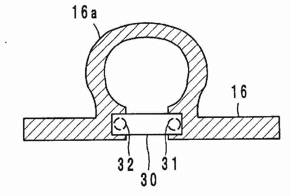
[0039] The details are as Figure 7 As shown, conductive patterns 16 and 17 connected to the power cable 15 and a conductive pattern 20 connected to the main body control circuit 5 are formed on the power substrate 11 , and a loop conductor 16 a is formed on the conductive pattern 16 . The wireless IC element 30 has a first terminal 31, a second terminal 32, and a third terminal 33, and the first and second terminals 31, 32 are coupled to the conductor pattern 16 (the root of the loop conductor 16a). In addition, the third terminal 33 is...
Embodiment 3
[0042] (Example 3, refer to Figure 8 and Figure 9 )
[0043] Such as Figure 8 As shown, in the electrical product 1C of Embodiment 3, the wireless IC component 30 is mounted on the power supply board 11, the wireless IC component 30 is coupled (directly or indirectly) to at least a part of the power supply cable 15, and the wireless IC component 30 is connected to the The main body control circuit 5 of the electrical product 1C is connected, and can further perform power line communication (Power Line Communication) with a server 55 via a power cable 15 .
[0044] The details are as Figure 9 As shown, conductive patterns 16 and 17 connected to the power cable 15 are formed on the power substrate 11 , and a ring-shaped conductor 16 a is formed on the conductive pattern 16 . The wireless IC element 30 has a first terminal 31, a second terminal 32, and a third terminal 33, and the first and second terminals 31, 32 are coupled to the conductor pattern 16 (the root of the l...
PUM
 Abstract
Description
Claims
Application Information
 - R&D
- Intellectual Property
- Life Sciences
- Materials
- Tech Scout
- Unparalleled Data Quality
- Higher Quality Content
- 60% Fewer Hallucinations
Browse by: Latest US Patents, China's latest patents, Technical Efficacy Thesaurus, Application Domain, Technology Topic, Popular Technical Reports.
© 2025 PatSnap. All rights reserved.Legal|Privacy policy|Modern Slavery Act Transparency Statement|Sitemap|About US| Contact US: help@patsnap.com