
Method for enlarging tuning range and improving phase noise performance of voltage-controlled oscillator

A voltage-controlled oscillator, tuning range technology, applied in power oscillators, electrical components, etc., can solve the problems of voltage-controlled oscillator phase noise reduction, phase noise difference, etc., to achieve low average power consumption, good phase noise, and energy saving The effect of power consumption

Active Publication Date: 2013-04-03
SHENZHEN INST OF ADVANCED TECH
View PDF2 Cites 5 Cited by
  • Summary
  • Abstract
  • Description
  • Claims
  • Application Information

AI Technical Summary

Problems solved by technology

In the current-limited region, the output amplitude of the voltage-controlled oscillator will decrease as the frequency decreases, which will cause the phase noise of the voltage-controlled oscillator to decrease, and the frequency range will increase, and its phase noise will also undergo relatively large changes. , especially at lower frequencies, its phase noise becomes worse

Method used


Image

  • Method for enlarging tuning range and improving phase noise performance of voltage-controlled oscillator
  • Method for enlarging tuning range and improving phase noise performance of voltage-controlled oscillator
  • Method for enlarging tuning range and improving phase noise performance of voltage-controlled oscillator

Examples


Embodiment Construction

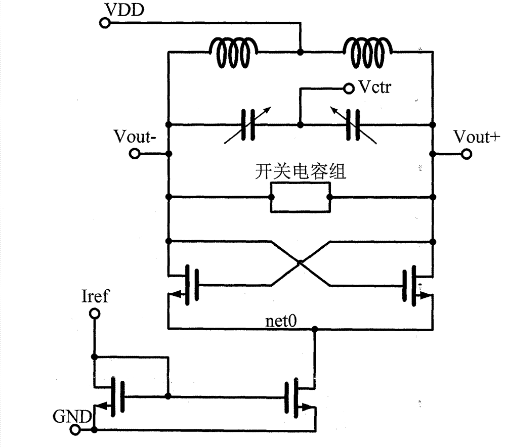
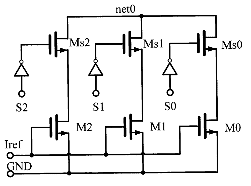
[0019] exist figure 1 In, is the structure diagram of the tail current biased oscillator, figure 1 Mainly explain the connection relationship between the switched capacitor bank and the switch bias current. A switched capacitor bank is connected between the two output ports Vout+ and Vout- of the oscillator, and a switched bias current is connected between net0 and GND of the oscillator.

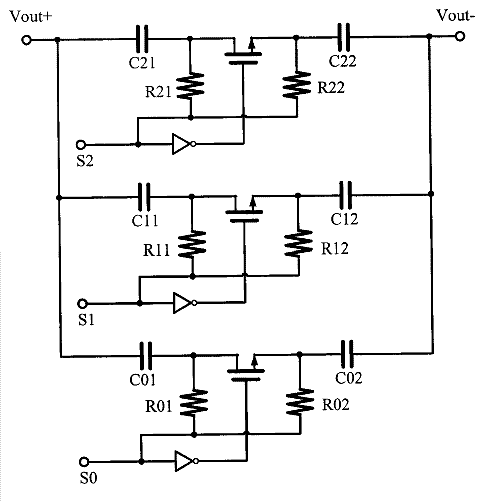
[0020] figure 2 A switched capacitor group is composed of three groups of switched capacitors, each group of switched capacitors is composed of two identical capacitors, two identical resistors, an NMOS transistor, and an inverter. Among them, the NMOS tube, two resistors, and the inverter constitute a switch, and the opening and closing of the switch is controlled by a digital signal. In order to reduce the number of digits of the digital control signal, a binary weighted capacitor array is used, and the value relationship of the three sets of capacitors is 2 n Doubling relationship (C...


PUM


Abstract

A method for enlarging a tuning range and improving a phase noise performance of a voltage-controlled oscillator mainly relates to a current bias type capacitance and inductance voltage-controlled oscillator, and particularly relates to a current bias type capacitance and inductance voltage-controlled oscillator in a current limitation region. A digital tuning module and a switch bias current module are adopted in the method, wherein the digital tuning module is used for enlarging the tuning range of the voltage-controlled oscillator through connection and disconnection of a switched capacitor; and the switch bias current module is used for increasing the phase noise of a whole system by connecting corresponding bias current in each frequency band. In the current limitation region, the output amplitude of the voltage-controlled oscillator decreases along with the reduction of frequency, so that the phase noise of the voltage-controlled oscillator is reduced; and simultaneously when the frequency range is enlarged, the phase noise also changes greatly, and particularly when the frequency is low, the phase noise becomes bad. According to the method, a wide turning rang is obtained through the coordination and adjustment of the digital tuning module and the switch bias current module, and the good phase noise is obtained in the whole frequency range.

Description

technical field [0001] The invention relates to a current-biased capacitive-inductive voltage-controlled oscillator, in particular to a current-biased capacitive-inductive voltage-controlled oscillator in a current-limited region. Background technique [0002] In recent years, with the prosperity of the communication market, wireless communication technology and related applications have developed rapidly. Personal wireless communication systems, wireless local area networks, satellite navigation systems (GPRS, Beidou system), satellite TV, radio frequency tags (RFID), and vehicle positioning systems have experienced rapid growth. At the same time, wireless communication technology has also been widely used in cutting-edge technologies such as electronic countermeasures and space technology. In these applications, the radio frequency front end is the key to the performance of these systems, so it has been the focus of research. [0003] In a wireless communication system, ...

Claims


Application Information

Patent Timeline
IPC IPC(8): H03B5/04
Inventor 盛志雄于峰崎
Owner SHENZHEN INST OF ADVANCED TECH
Learn More