


Quick Research
Generate reliable direction feasibility study reports for your R&D in just a few steps.

Technical Q&A
Discover and master advanced knowledge NOW. Basics, ideas, possibilities, all at once.

Find Solutions
As an expert in R&D theories, this can generate solutions to your technical problems instantly.

Evaluate Feasibility
Analyze your overall solution with one click, know your potential R&D risks in advance.

Monitor Landscape
Get weekly tech updates, stay abreast of the latest tech innovations and key insights.
An ion trap device with stepped grid electrode structure
A technology of grid electrodes and ion traps, which is applied to parts of particle separator tubes, dynamic spectrometers, trajectory-stabilized spectrometers, etc., can solve problems such as limited ion intensity, improve mass resolution, and reduce electric field loss and distortion, improving ion storage and mass analysis performance
- Summary
- Abstract
- Description
- Claims
- Application Information
AI Technical Summary
Problems solved by technology
Method used
Image

Examples
specific Embodiment 1
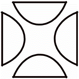
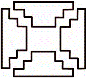
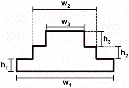
[0039] Specific embodiment 1 reference Figure 4 — Figure 6 shown, where Figure 4 It is a three-dimensional structural diagram of the ion trap of this solution, which is composed of six electrodes, which are a pair of electrodes 102 and 103 in the z direction, and the electrode shape is a flat plate electrode. The electrode 102 is provided with a through hole (aperture), the size of which is several millimeters, for introducing the sample ions 101 . A pair of electrodes 106 and 107 in the x direction, a pair of electrodes 104 and 105 in the y direction. Define the x-direction to be the direction in which ions are ejected. Electrodes 106 and 107 are stepped electrodes loaded with grids, and grids 108 are positioned on the highest step surface, such as Figure 6 shown. The grid covering the electrode part is processed into a cavity structure. The electrodes 104 and 105 are stepped electrodes not loaded with a grid. Figure 5 It is a cross-sectional view of the center of...
Embodiment 2
[0042] Figure 10 — Figure 11 Shown is the schematic structural view of the ion trap device of specific embodiment 3, wherein Figure 10 It is a three-dimensional structural diagram of the ion trap of this solution, which is composed of six electrodes, which are a pair of electrodes 302 and 303 in the z direction, and the electrode shape is a flat plate electrode. An aperture is opened on the electrode 302 for introducing sample ions 401 . A pair of electrodes 306 and 307 in the x direction, a pair of electrodes 304 and 405 in the y direction. Define the x-direction to be the direction in which ions are ejected. The electrodes 305 , 306 , and 307 in the entire ion trap are all step grid electrodes, and the grid cover electrodes are processed into a cavity structure. The electrode 304 is a stepped electrode without a grid. Figure 11 It is a two-dimensional cross-sectional schematic diagram of an electrode pair in the x and y directions at the center of the ion trap. The ...
Embodiment 3
[0044] Figure 12 — Figure 13 Shown is the structural representation of the ion trap device of specific embodiment 4, wherein Figure 12 It is a three-dimensional structural diagram of the ion trap of this solution, which is composed of six electrodes, which are a pair of electrodes 402 and 403 in the z direction, and the electrode shape is a flat plate electrode. An aperture is opened on the electrode 402 for introducing sample ions 401 . A pair of electrodes 406 and 407 in the x direction, a pair of electrodes 404 and 405 in the y direction. Define the x-direction to be the direction in which ions are ejected. The electrodes 404 , 405 , 406 , and 407 in the entire ion trap are stepped electrodes loaded with grids, and the grids cover the electrode parts processed into hollows. Figure 13 It is a two-dimensional cross-sectional schematic diagram of the electrode pair in the x and y directions at the center of the ion trap. The two pairs of electrodes are symmetrically d...
PUM
 Abstract
Description
Claims
Application Information
 - R&D Engineer
- R&D Manager
- IP Professional
- Industry Leading Data Capabilities
- Powerful AI technology
- Patent DNA Extraction
Browse by: Latest US Patents, China's latest patents, Technical Efficacy Thesaurus, Application Domain, Technology Topic, Popular Technical Reports.
© 2024 PatSnap. All rights reserved.Legal|Privacy policy|Modern Slavery Act Transparency Statement|Sitemap|About US| Contact US: help@patsnap.com