Station device for powder coating of energy-saving lamps

An energy-saving lamp and station technology, which is applied in the application of luminescent coatings, tube/light screen manufacturing, etc., can solve the problems of low slurry outflow, low recovery and utilization rate of slurry, and inability to effectively control the thickness of powder coating. Easy to adjust, convenient upper and lower tube effect

Inactive Publication Date: 2015-12-30
XIAMEN WEI MING DA ELECTRICAL EQUIP
View PDF5 Cites 0 Cited by
  • Summary
  • Abstract
  • Description
  • Claims
  • Application Information

AI Technical Summary

Problems solved by technology

[0004] 1. The lamp tube opening of the powder coating station faces inward, so that during the powder coating process, it is easy to flow the powder slurry along the work rod to the station and the machine. The recycling rate of the powder slurry is low, and it affects the cleanliness and convenience of the machine beautiful;
[0005] 2. The blowing pipe of the existing station device for powder coating of energy-saving lamps is a stainless steel pipe, which is inconvenient to adjust so that it is aligned with the mouth of the lamp pipe for blowing;
[0006] 3. The station frame for fixing the lamp tube is fixed, the outflow of the powder slurry in the lamp tube is very small, and the thickness of the powder coating cannot be effectively controlled

Method used


Image

  • Station device for powder coating of energy-saving lamps
  • Station device for powder coating of energy-saving lamps
  • Station device for powder coating of energy-saving lamps

Examples


Embodiment

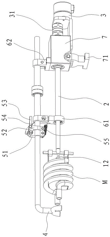
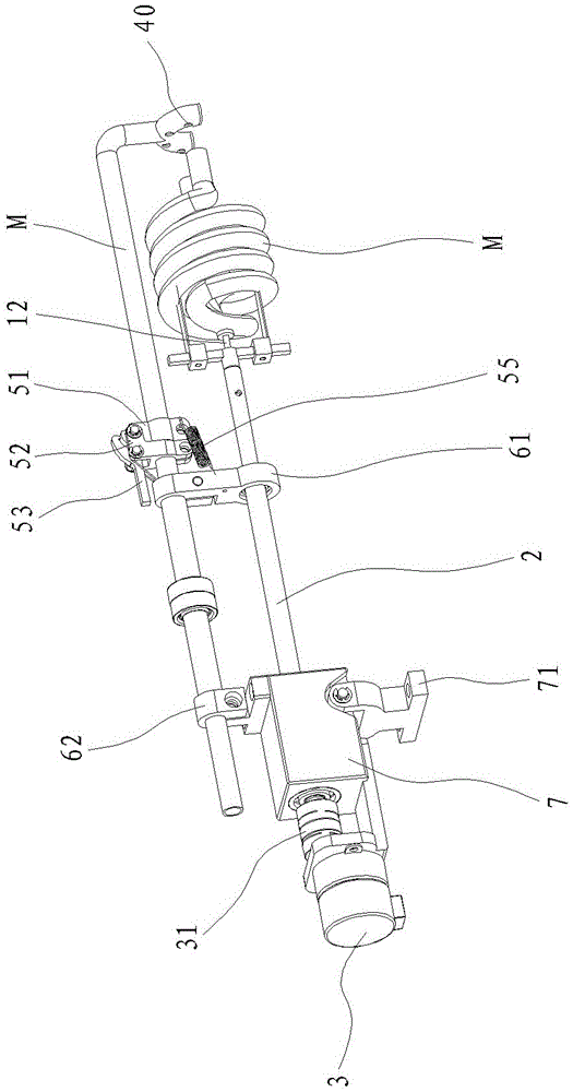
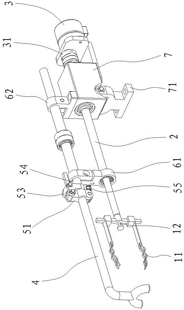
[0029] Example: see Figure 1 to Figure 5 , a station device for powder coating of an energy-saving lamp, comprising a station frame 1, a station rod 2, a drive motor 3 and a blowpipe 4, wherein:

[0030] A station frame 1, which fixes the lamp tube M and makes the lamp tube mouth face outward, and the station frame 1 is connected with the station rod 2;

[0031] The station rod 2 is driven by the drive motor 3 provided at the rear end and drives the station frame to rotate. The center axis of the front end of the station rod is provided with a shaft hole for accommodating the limit rod 12. The limit rod can move along the working direction. The position rod moves vertically;

[0032] The blowing pipe 4 is arranged in parallel with the station bar 2 and fixed as a whole by a connecting piece. The blowing pipe extends forward to the front end of the station frame and is bent to form a blowing port 40. Powder job.

[0033] see Figures 1 to 5 The blowing pipe 4 of the presen...


PUM


Abstract

The invention discloses a workstation device for powdering an energy-saving lamp. The workstation device comprises a workstation frame, a workstation rod, a driving motor and a blowpipe, the workstation frame fixes a lamp pipe, enables an opening of the lamp pipe to be outward and is connected with the workstation rod which is driven by the driving motor arranged at the rear end and drives the workstation frame to rotate, a shaft hole used for containing a limiting rod is arranged axially at the center of the front end of the workstation rod, the limiting rod can move longitudinally along the workstation rod and controls slurry thickness of the lamp pipe, and a blowing port of the blowpipe performs powdering operations facing at the outward opening of the lamp pipe. The blowpipe can be adjusted to align to a pipe opening for blowing, and the outward opening of the lamp pipe is easier to recover the slurry.

Description

technical field [0001] The invention discloses a station device for powder coating of energy-saving lamps, which belongs to the technical field of powder coating equipment for energy-saving lamps according to the International Patent Classification (IPC). Background technique [0002] The powder coating process of the energy-saving lamp tube is to coat a layer of fluorescent powder on the inner wall of the transparent spiral tube. At present, there are generally two methods of powder coating: static powder coating and dynamic powder coating. Among them, static powder coating is easy to produce powder accumulation on the inner wall of the tube, which reduces the light efficiency of the lamp tube, and at the same time wastes fluorescent powder, resulting in high production costs; dynamic powder coating. The powder coating process has a better coating effect and has become the main process used in the production of energy-saving lamps. [0003] However, the existing energy-sav...

Claims


Application Information

Patent Timeline
Patent Type & Authority Patents(China)
IPC IPC(8): H01J9/22
Inventor 叶开发练小红
Owner XIAMEN WEI MING DA ELECTRICAL EQUIP
Why Eureka
Try Eureka