
Steady state visual evoked potential brain-computer interface signal identification method

A steady-state visual induction and signal recognition technology, applied in the field of neural engineering, can solve problems such as myoelectric signal interference, classification errors, and unstable EEG signals

Active Publication Date: 2013-04-03
PEKING UNIV
View PDF6 Cites 20 Cited by
  • Summary
  • Abstract
  • Description
  • Claims
  • Application Information

AI Technical Summary

Problems solved by technology

[0005] The brain-computer interface system with steady-state visual evoked potential as the input signal has the advantages of high information transmission rate, short training time, and easy feature extraction. However, due to the instability of EEG signals and the interference of EMG signals, There are often some errors in the classification

Method used


Image

  • Steady state visual evoked potential brain-computer interface signal identification method
  • Steady state visual evoked potential brain-computer interface signal identification method
  • Steady state visual evoked potential brain-computer interface signal identification method

Examples


Embodiment Construction

[0031] DETAILED DESCRIPTION OF THE PREFERRED EMBODIMENTS The preferred embodiments of the present invention will be described in more detail below with reference to the accompanying drawings of the present invention.

[0032] A brain-computer interface method based on active confirmation of steady-state visual evoked potentials, comprising the following steps:

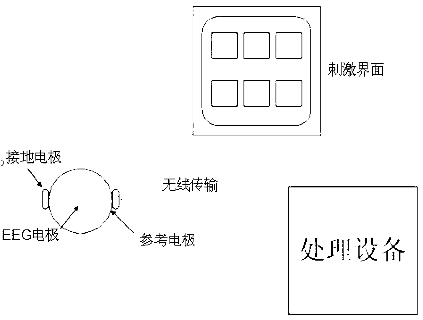
[0033] Step 1: In the occipital lobe O of the subject's head Z An electroencephalograph electrode (EEG electrode) is placed at the position, a reference electrode is placed at the position of one ear pinna, and a grounding electrode is placed at the position of the other ear pinna. signal (such as figure 2 and image 3 ), and use wireless devices and computers for data transmission, and use computers to store the collected EEG signals.

[0034] Step 2: Use the display screen to display the stimulus picture. First, the display screen will display a black screen for 10s. The purpose is to record the resting EEG signa...


PUM


Abstract

The invention discloses a steady state visual evoked potential brain-computer interface signal identification method, which comprises the following steps of: (1) simultaneously displaying a plurality of different pictures with different flicker frequencies through a visual stimulation unit and acquiring electroencephalogram signals of a testee who stares at the visual stimulation unit; (2) carrying out noise estimation and noise suppression on the electroencephalogram signals by a data processing unit, and then carrying out characteristic extraction and judgment on the processed electroencephalogram signals to primarily determine the picture at which the testee stares; and (3) upsetting the flicker frequencies of the displayed pictures, acquiring the electroencephalogram signals, then carrying out noise estimation and noise suppression on the currently acquired electroencephalogram signals, then carrying out characteristic extraction and judgment on the processed electroencephalogram signals to determine the picture at which the testee stares, if the currently determined picture is the same as the picture determined in the step 2, taking the picture as finally determined identification information to output, and if not, judging that the testee does not stare at any picture displayed by the visual stimulation unit. According to the steady state visual evoked potential brain-computer interface signal identification method, the electroencephalogram signal identification accuracy can be effectively improved.

Description

technical field [0001] The invention belongs to the technical field of neural engineering, and in particular relates to a steady-state visual evoked potential and a brain-computer interface signal recognition method. Background technique [0002] Brain-Computer Interface (BCI) is a system that realizes direct communication and control between the brain and computers or other devices based on EEG signals. The brain-computer interface can directly convert the information sent by the brain into commands that can drive external devices, and can replace human limbs to realize the communication between human and the external world and the control of the external environment. The brain-computer interface system has opened up a new way for the human brain to communicate and control information with the outside world, making it possible to use human brain signals to directly control external devices. [0003] Currently, there are two types of brain-computer interface systems: invasi...

Claims


Application Information

Patent Timeline
Patent Type & Authority Applications(China)
IPC IPC(8): G06F3/01
Inventor 吴玺宏朱风云张广程
Owner PEKING UNIV
Learn More