Swash plate piston hydraulic transformer controlled by swing hydraulic motor
A technology of swinging hydraulic motors and hydraulic transformers, applied in the field of hydraulic transformers, can solve the problems of unfavorable system automation flow and precise pressure control, and achieve the effects of no throttling loss, integration, and simple flow distribution structure
- Summary
- Abstract
- Description
- Claims
- Application Information
AI Technical Summary
Problems solved by technology
Method used
Image
Examples
specific Embodiment approach 1
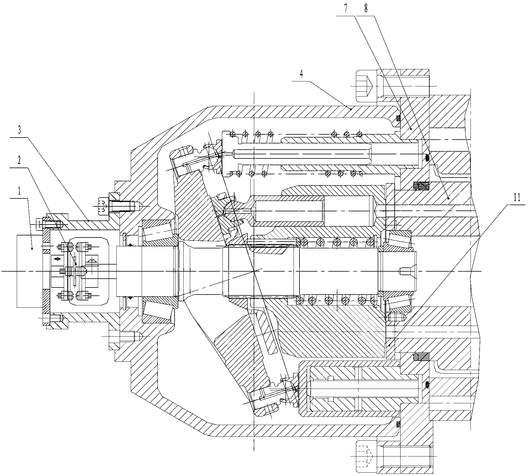
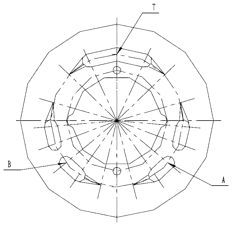
[0009] Specific implementation mode one: combine figure 1 and figure 2 The present embodiment will be described. In the hydraulic transformer of the present embodiment, the flow plate 11 is mounted on the main shaft 8 of the swing hydraulic motor.
specific Embodiment approach 2
[0010] Specific implementation mode two: combination figure 1 Describe this embodiment, the transformer of this embodiment also includes a photoelectric encoder 1 and a mounting bracket 3, the casing of the photoelectric encoder 1 is mounted on the casing of the hydraulic transformer through the mounting bracket 3, and the rotor of the photoelectric encoder 1 is connected through an elastic coupling The device 2 is connected with the main shaft transmission of the swash plate plunger pump body 4 of the hydraulic transformer, and this structure realizes the measurement of the rotational speed of the hydraulic transformer. Other implementation manners are the same as the specific implementation manner 1.
specific Embodiment approach 3
[0011] Specific implementation mode three: combination figure 1 Describe this embodiment, the end cover 7 of the swing hydraulic motor of this embodiment is connected with the swash plate plunger type pump body 4 of the hydraulic transformer, the rear end cover of the swash plate plunger type pump body is omitted, and the hydraulic transformer is reduced. The axial dimension realizes the integrated design of the structure. Other implementation manners are the same as the specific implementation manner 1.
[0012] How it works: combined figure 1 and figure 2 Note that when the hydraulic transformer is connected to the hydraulic system, the pressure of the constant pressure network is connected to the distribution port A of the swing hydraulic motor shaft 8, the load end is connected to the distribution port B of the swing hydraulic motor shaft 8, and the low pressure end is connected to the swing hydraulic motor shaft 8, because the shaft 8 of the swing hydraulic motor is c...
PUM
 Abstract
Description
Claims
Application Information
 - R&D
- Intellectual Property
- Life Sciences
- Materials
- Tech Scout
- Unparalleled Data Quality
- Higher Quality Content
- 60% Fewer Hallucinations
Browse by: Latest US Patents, China's latest patents, Technical Efficacy Thesaurus, Application Domain, Technology Topic, Popular Technical Reports.
© 2025 PatSnap. All rights reserved.Legal|Privacy policy|Modern Slavery Act Transparency Statement|Sitemap|About US| Contact US: help@patsnap.com


