
Stay cable device for kilometric cable stayed bridge and mounting method thereof

An installation method and cable-stayed technology, which are applied in bridges, bridge parts, bridge construction, etc., can solve the problems of difficult construction of gravity anchors, poor durability of sag effect, and difficult structure of cable-stayed bridges. The effect of optimizing the combined effect, improving the equivalent stiffness, and improving the mechanical properties

Inactive Publication Date: 2013-04-03
SOUTHEAST UNIV
View PDF4 Cites 5 Cited by
  • Summary
  • Abstract
  • Description
  • Claims
  • Application Information

AI Technical Summary

Problems solved by technology

However, these areas are often on soft soil foundations with poor bearing capacity or poor geological conditions. It is extremely difficult to construct super-large-scale gravity anchorages, and the cost is very expensive, so it is not the best solution. bridge will be highly competitive
[0005] In order to further increase the span of cable-stayed bridges, the structure of traditional steel-stayed cable-stayed bridges is very difficult; CFRP is light, high-strength, and corrosion-resistant. It can be used as a cable-stayed cable material to solve the self-heaviness and sag effects of traditional steel cable-stayed cables. Obvious and poor durability, but its elastic modulus is low. Generally speaking, within the horizontal span of 2000m cable-stayed cables or the range of 4000m main-span cable-stayed bridges, even if the sag effect of CFRP cable-stayed cables is small, its equivalent stiffness is still Obviously lower than traditional steel cable-stayed cables, it is difficult to be directly applied in current kilometer-level cable-stayed bridges (1000~3000m main span)

Method used


Image

  • Stay cable device for kilometric cable stayed bridge and mounting method thereof
  • Stay cable device for kilometric cable stayed bridge and mounting method thereof
  • Stay cable device for kilometric cable stayed bridge and mounting method thereof

Examples


Embodiment Construction

[0035] The technical solution of the present invention will be described in detail below in conjunction with the accompanying drawings.

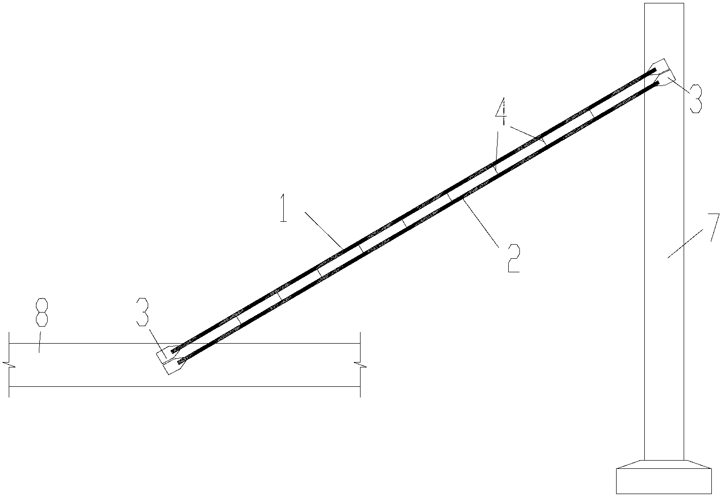
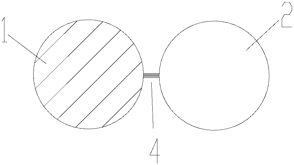
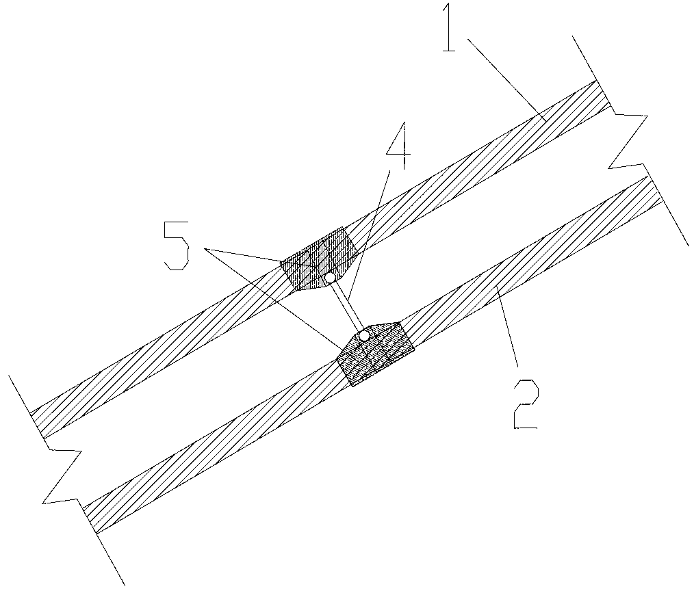
[0036] like Figure 1 to Figure 4As shown, a kind of cable-stayed device for the kilometer-level cable-stayed bridge of the present invention comprises the first cable-stayed cable 1 and the second cable-stayed cable 2 that are positioned at the same cable position, and the first cable-stayed cable 1 is made of steel The second stay cable 2 is made of carbon fiber reinforced composite material, and the two ends of the first stay cable 1 and the second stay cable 2 are respectively fixedly connected to the bridge structure through anchoring devices. The bridge structure mainly includes a main tower 7 and a main girder 8 . The tension end of the first stay cable 1 and the tension end of the second stay cable 2 are fixedly connected to the main tower 7 respectively, and the anchor end of the first stay cable 1 and the anchor end of the second ...


PUM


Abstract

The invention discloses a stay cable device for a kilometric cable stayed bridge, which comprises a first stay cable and a second stay cable which are located at the same cable position. The first stay cable is made of steel, and the second stay cable is made of a carbon fiber reinforced composite material; and two ends of the first stay cable and the second stay cable are fixedly connected with a bridge structure respectively by an anchor device. The stay cable device can effectively improve the mechanical property of the kilometric cable stayed bridge and reduce the cost. Meanwhile, the invention also discloses a mounting method for the stay cable device, which comprises the following steps: step 10) determining a section area proportion of the stay cable of the first stay cable and the second stay cable; step 20) determining a cable tension force of the first stay cable and a cable tension force of the second stay cable; step 30) anchoring the first stay cable and the second stay cable on the bridge; and step 40) arranging a connecting device between the first stay cable and the second stay cable. The mounting method can greatly reduce the self weight of hybrid cables and reduce a sag effect.

Description

technical field [0001] The invention relates to a cable-stayed device, in particular to a cable-stayed device for a kilometer-level cable-stayed bridge, and at the same time, the invention also relates to an installation method of the cable-stayed device. Background technique [0002] Since the first modern cable-stayed bridge was built in 1956, cable-stayed bridges have developed rapidly. Because the cable-stayed bridge has the advantages of high structural rigidity, convenient construction, and good economy, it has basically replaced the suspension bridge below 600 meters, and is also very competitive within the span of 600 to 1000 meters. The completion of the Sutong Bridge has brought the span of the cable-stayed bridge into the era of over one kilometer. Studies have shown that ultra-kilometre-scale cable-stayed bridges still have competitive advantages compared with suspension bridges in terms of mechanical properties and economics, so it can be expected that cable-st...

Claims


Application Information

Patent Timeline
Patent Type & Authority Applications(China)
IPC IPC(8): E01D19/16E01D21/00
Inventor 熊文叶见曙
Owner SOUTHEAST UNIV
Learn More