
Control method and device of electric precipitator in sintering system

A technology of electrostatic precipitator and rapping device, applied in the direction of power supply technology, electrostatic separation, etc., can solve problems such as energy waste, achieve the effects of avoiding waste of electric energy, overcoming waste of electric energy, and reducing energy consumption of dust removal

Active Publication Date: 2013-04-03
ZHONGYE-CHANGTIAN INT ENG CO LTD
View PDF5 Cites 9 Cited by
  • Summary
  • Abstract
  • Description
  • Claims
  • Application Information

AI Technical Summary

Problems solved by technology

[0006] The inventor found in the process of realizing the present invention that the electrostatic precipitator is generally designed under the design parameters such as the most conservative design discharge, maximum dust content, and maximum air flow, so as to ensure reliable operation under the most unfavorable conditions However, due to changes in production, the actual flue gas handling capacity of the electrostatic precipitator is quite different from the designed handling capacity. It often works under the actual working condition of low load, but still operates according to the working condition of the maximum flue gas handling capacity, that is, the maximum load to run, resulting in a large waste of energy

Method used


Image

  • Control method and device of electric precipitator in sintering system
  • Control method and device of electric precipitator in sintering system
  • Control method and device of electric precipitator in sintering system

Examples


Embodiment 1

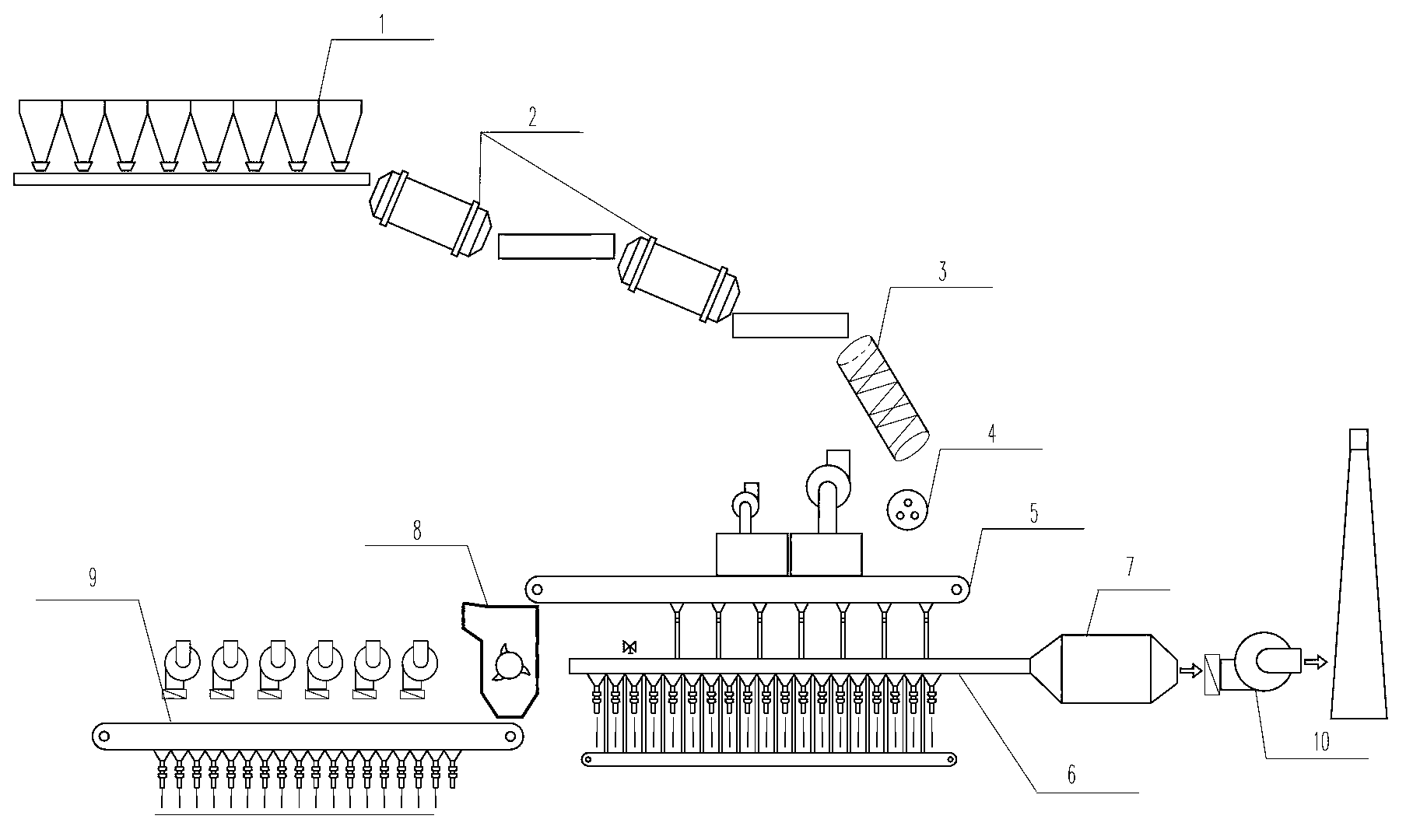
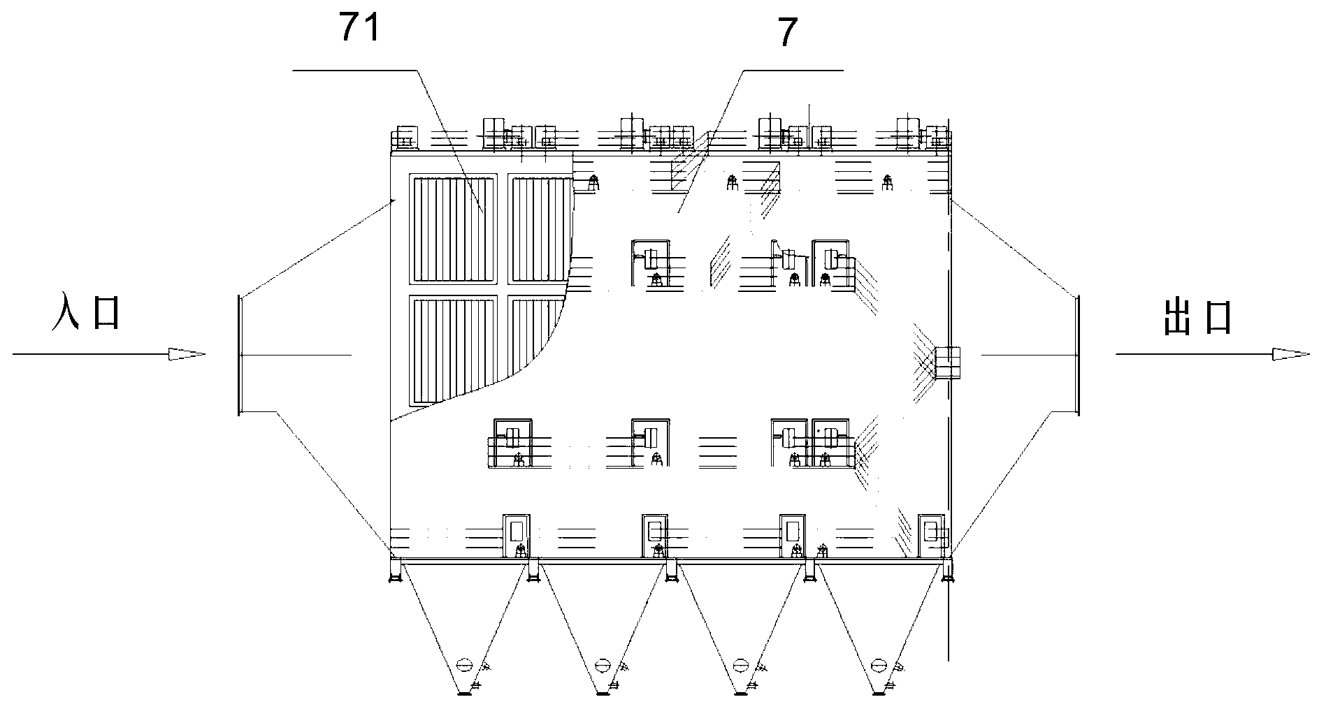
[0066] Due to changes in production, the flow rate and dust content of the exhaust gas in the main flue of the sintering machine will also change greatly. The general electrostatic precipitator is designed to consider the dust removal requirements under the maximum production capacity, so many times the actual The working condition has not reached full load, and the electrostatic precipitator is still working at full load at this time, resulting in a lot of waste of electric energy. Even if the electrostatic precipitator is adjusted according to experience, it is obvious that the effect of energy saving will basically not be achieved due to large errors. However, in this embodiment, through the acquisition and analysis of field working condition data, more accurate control of the electrostatic precipitator is realized, and energy consumption for dust removal is reduced.

[0067] The electrostatic precipitator is a metal anode and cathode with a large difference in curvature ra...

Embodiment 2

[0106] The operation process of electrostatic precipitator is a dynamic process, and different working conditions should have different optimal operating parameters and different operating modes. As the amount of material increases, the high specific resistance dust in the flue gas dust also increases. Back corona is prone to occur during the dust collection process, resulting in a sharp drop in dust removal efficiency.

[0107] Theory and practice show that intermittent pulse power supply can effectively overcome the back corona caused by dust with high specific resistance, and the duty ratio of intermittent pulse power supply is 1:2, 1:4, 1:6, 1:8...1:20 and 2:2, 2:4, 2:6, 2:8...2:20 etc. In this embodiment, a duty ratio setting database can be established according to the on-site production conditions and the volt-ampere characteristics of the electric field. Then after the amount of sintering material is obtained, compare the data of the amount of sintering material with t...

Embodiment 3

[0112] Too much or too little rapping will greatly affect the dust removal effect. If the frequency of rapping is too small, it will cause serious dust accumulation on the dust collection plate, resulting in a serious decrease in the secondary current and a decrease in the dust removal efficiency. Too much rapping will cause secondary dust in the electric field, resulting in a decrease in dust removal efficiency. Therefore, proper rapping control can not only ensure the operation of the dust collector in a high-efficiency state, but also achieve energy-saving effects.

[0113] see Figure 5 As shown, on the basis of Embodiment 1, the electrostatic precipitator may also include a rapping device, and after step S301, the method may also include the following steps:

[0114] S309. Obtain a third correlation coefficient between the amount of sintered material and the rapping frequency.

[0115] S310. Obtain a rapping frequency by multiplying the amount of sintered material by t...


PUM


Abstract

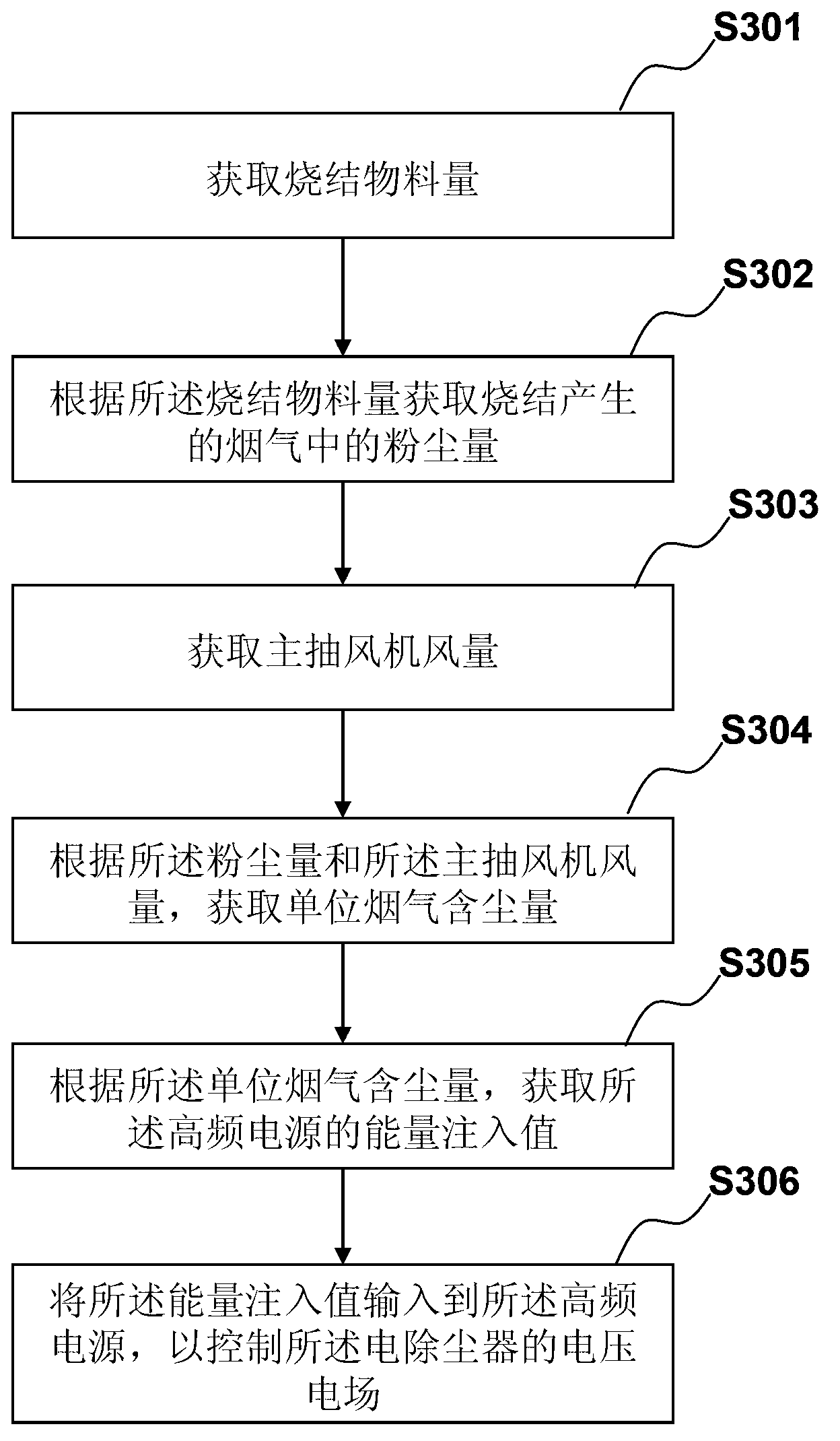
The embodiment of the invention discloses a control method and device of an electric precipitator in a sintering system. The electric precipitator comprises a high-frequency power source. The control method comprises the following steps of: acquiring the quantity of sintered materials; acquiring the dust capacity in exhaust gas generated in sintering according to the quantity of the sintered materials; acquiring the air quantity of a main exhaust fan; acquiring a dust content of unit exhaust gas according to the dust capacity and the air quantity of the main exhaust fan; acquiring the energy adding value of the high-frequency power source according to the dust content of the unit exhaust gas; and inputting the energy adding value into the high-frequency power source to control a voltage electric field of the electric precipitator. According to the control method and device of the electric precipitator in the sintering system, the energy adding value is regulated to control and regulate the voltage electric field of the electric precipitator by acquiring actual working condition data such as the quantity of the sintered materials and the air quantity of the main exhaust fan, and the electric precipitator can efficiently run in an energy-saving manner, thereby solving the problem of electric energy waste because the field handling capacity of the exhaust gas of the electric precipitator does not reach a designed handling capacity in an actual production process, and reducing the energy consumption of dust extraction.

Description

technical field [0001] The invention relates to the energy-saving technology of a sintering system in the field of metallurgy, in particular to a control method and a control device for an electric dust collector in a sintering system. Background technique [0002] With the rapid development of modern industry, the scale of steel production is getting larger and larger, and energy consumption is also increasing. Energy conservation and environmental protection have become important indicators of steel production. In iron and steel production, iron-containing raw material ores need to be processed by a sintering system before entering the blast furnace for smelting. In the iron and steel metallurgical industry, before the iron-containing raw material ore enters the blast furnace for smelting, it is necessary to mix various powdery iron-containing raw materials with an appropriate amount of fuel and flux, add an appropriate amount of water, and mix and pelletize the material o...

Claims


Application Information

Patent Timeline
IPC IPC(8): B03C3/68
Inventor 申伟杰袁立新孙超卢杨权高鹏双刘国同
Owner ZHONGYE-CHANGTIAN INT ENG CO LTD
Learn More