
Active optical fiber structure for gaining application and achieving method thereof

An optical fiber structure and optical fiber preform technology, which can be used in multi-layer core/cladding optical fibers, graded index core/cladding optical fibers, applications, etc., and can solve the problem of fiber strength and bending resistance. Improve the production yield and other problems, to achieve the effect of low splicing loss, reducing splicing loss, and improving refractive index difference

Inactive Publication Date: 2013-03-27
CHINA ELECTRONICS TECH GRP NO 23 RES INST
View PDF4 Cites 7 Cited by
  • Summary
  • Abstract
  • Description
  • Claims
  • Application Information

AI Technical Summary

Problems solved by technology

[0005] In the prior art, although the method of designing a polygonal inner cladding structure with a different shape can improve the pumping efficiency of the double-clad fiber, it also has many shortcomings.
Such a structural design requires optical processing of the quartz optical fiber preform, and due to the influence of stress on the quartz material, it is very easy to crack during optical processing and polishing, resulting in a very low production rate; and due to the polishing of the surface of the preform treatment, it is easy to cause the surface to be unclean, and impurity particles such as polishing powder and corundum are introduced, resulting in an increase in fiber loss; because the shape of the quartz cladding of the double-clad fiber is irregular and polygonal, the strength and bending resistance of the fiber are greatly reduced ; The special-shaped polygonal cladding structure also causes the improvement of the optical fiber fusion splicing loss

Method used


Image

  • Active optical fiber structure for gaining application and achieving method thereof
  • Active optical fiber structure for gaining application and achieving method thereof
  • Active optical fiber structure for gaining application and achieving method thereof

Examples

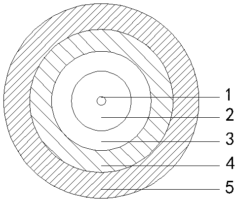
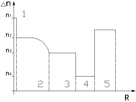

Embodiment 1

[0026] The graded-index cladding active optical fiber shown in Example 1 has a core diameter of 11 μm, a core numerical aperture (NA) of 0.07, a graded-index inner cladding diameter of 75 μm, a silica cladding diameter of 125 μm, and a circular silica cladding shape. , the optical fiber is coated with an outer diameter of 245 μm. The measured absorption coefficient of the fiber at 915nm is 1.8dB / m, and the slope efficiency of the fiber laser made from a 7m fiber is 75.6%.

[0027] The double-clad active optical fiber preform of Example 1 is manufactured by using MCVD or PCVD technology. When making an optical fiber preform, firstly, a graded-refractive-index inner cladding 2 with a higher refractive index than the quartz outer cladding 3 (deposition tube) is deposited in the deposition tube. The deposition process is SiCl 4Flow remains constant at 600sccm, GeCl 4 The initial flow rate is 30sccm, and 40 layers are deposited incrementally per layer at a flow rate of 2sccm, and...

Embodiment 2

[0029] The graded-index cladding active fiber of Example 2 has a core diameter of 11 μm, a core numerical aperture (NA) of 0.07, a diameter of graded-index silica cladding of 125 μm, a circular cladding shape, and an optical fiber coating outer diameter of 245 μm. The measured absorption coefficient of the fiber at 915nm is 1.9dB / m, and the slope efficiency of the fiber laser made from a 7m fiber is 77%.

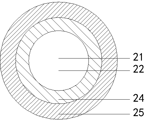
[0030] Embodiment 2 is manufactured by PCVD process. When the optical fiber preform is made, a graded-refractive-index quartz cladding 22 with a lower refractive index than the quartz deposition tube is deposited in the deposition tube, and the deposition process is SiCl 4 The flow remains constant at 600sccm, C 2 f 6 The initial flow rate is 100 sccm, and 1000 layers are deposited in each layer at a flow rate of 0.06 sccm, and then 1000 layers are deposited at a flow rate of 0.03 sccm for each layer, and then 500 layers are deposited at a flow rate of 0.01 sccm for each l...


PUM

PropertyMeasurementUnit
Diameteraaaaaaaaaa
Diameteraaaaaaaaaa
Outer diameteraaaaaaaaaa

Abstract

The invention relates to fiber lasers, provides an active optical fiber structure for gaining an application and an achieving method thereof, so that a quite high coupling efficiency of fiber cores to covering pump lights can be achieved even though an internal covering is not needed to be designed into a polygon structure such as an octagon or a D-type. The structured is characterized by comprising a fiber core, a quartz covering, a low-refractive-index cladding and an external cladding which form a concentric circular layer structure from inside to outside, wherein the quartz covering can be formed either by only one layer of quartz covering with a graded refractive index or by a layer of internal quartz covering with a graded refractive index and a layer of external quartz covering, while the refractive indexes at any position of the internal quartz covering are all higher than the refractive index of the external quartz covering. According to the structure and the method, the problems of high welding loss, high bending loss, low strength and the like of the active optical fiber in the prior art are solved, the production process for the active optical fiber is simplified, and significance is provided for fiber lasers.

Description

technical field [0001] The present invention relates to fiber lasers, and more particularly to active fibers used in fiber lasers to efficiently couple pump radiation into the fiber gain core. The optical fiber structure can be used in the manufacture of optical fiber couplers, optical fiber gratings, optical fiber isolators and passive optical fibers for energy transmission. technical background [0002] Fiber laser refers to a laser that uses optical fiber as the laser medium. By doping rare earth ions in the fiber core, such as Yb, Er, Tm, Ho, etc., the laser gain output of the corresponding wavelength is obtained. Compared with traditional solid-state lasers, fiber lasers have the advantages of good heat dissipation, high conversion efficiency, and good beam quality. [0003] For conventional single-mode fiber lasers, the pump light injected into the fiber core must be single-mode, which limits the efficiency of the pump light into the fiber, resulting in low output pow...

Claims


Application Information

Patent Timeline
IPC IPC(8): G02B6/028G02B6/036C03B37/014C03B37/02
CPCC03B2201/12C03B2201/32C03B2203/26C03B2201/31C03B2201/36C03B37/01807C03B2201/34C03B2201/28C03B2203/22Y02P40/57
Inventor 潘志勇朱源
Owner CHINA ELECTRONICS TECH GRP NO 23 RES INST
Learn More