LED (Light-Emitting Diode) lamp bulb heat radiation lamp cup

A technology of LED light bulbs and lamp cups, applied in lighting and heating equipment, cooling/heating devices of lighting devices, point light sources, etc., can solve the problems of complicated production, scratching hands, and high cost, and improve the simplicity of assembly , Strengthen the heat dissipation and strength, and the effect of good heat conduction and heat transfer performance

Inactive Publication Date: 2013-03-27
BYD CO LTD
View PDF6 Cites 8 Cited by
  • Summary
  • Abstract
  • Description
  • Claims
  • Application Information

AI Technical Summary

Problems solved by technology

Disadvantages When a single fin forms a fin group, welding is required, which is complicated to manufacture and high in cost; at the same time, the fins are made of metal as a whole, and the edges have the risk of conducting electricity and scratching hands; in addition, the fin group needs to be welded and fixed on the On the fixed bottom plate, the contact thermal resistance of the connection part is also too large, which affects the heat conduction and heat transfer performance of the lamp cup
[0005] The inventors of the present application found that: in the structure of the LED light bulb produced by the above two methods, the methods of extrusion molding and fin molding need to form two parts, the heat dissipation lamp cup and the fixed base, and the two parts are mechanically combined At the same time, the production and assembly process is complicated, and at the same time, due to the excessive contact thermal resistance of the connecting part, it will affect the heat conduction and heat transfer performance of the LED cooling lamp cup

Method used


Image

  • LED (Light-Emitting Diode) lamp bulb heat radiation lamp cup
  • LED (Light-Emitting Diode) lamp bulb heat radiation lamp cup
  • LED (Light-Emitting Diode) lamp bulb heat radiation lamp cup

Examples


Embodiment Construction

[0014] In order to make the technical problems, technical solutions and beneficial effects solved by the present invention clearer, the present invention will be further described in detail below in conjunction with the embodiments. It should be understood that the specific embodiments described here are only used to explain the present invention, not to limit the present invention.

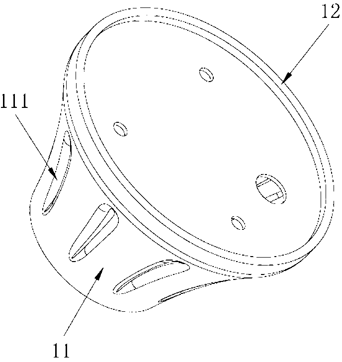
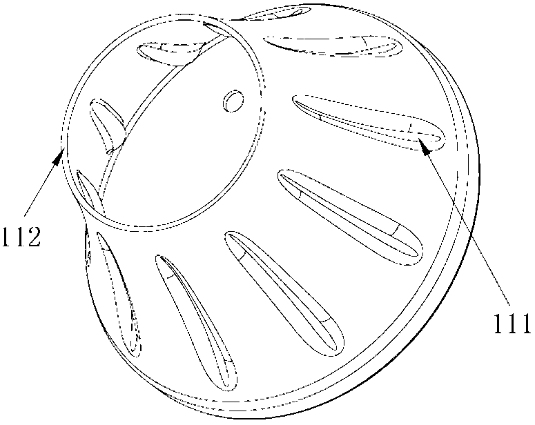
[0015] Please refer to figure 1 and figure 2 As shown, a heat dissipation lamp cup for an LED light bulb includes a metal heat dissipation lamp cup main body 11 and a fixed base plate 12. The outer surface of 11 is provided with a reinforcing part 111 for dissipating heat and increasing strength.

[0016] In the heat dissipation lamp cup for LED light bulbs provided by the present invention, the metal heat dissipation lamp cup body and the fixed bottom plate are integrally stamped and formed by the same material, which can avoid the thermal conductivity caused by the combination between the he...


PUM


Abstract

The invention provides an LED (Light-Emitting Diode) lamp bulb heat radiation lamp cup, comprising a metal heat radiation lamp cup main body and a fixing bottom plate, wherein the metal heat radiation lamp cup main body and the fixing bottom plate are integrally punched and molded by using the same materials; and a heat radiation part for radiating heat is arranged on the outer surface of the metal heat radiation lamp cup main body. According to the LED lamp bulb heat radiation lamp cup, the metal heat radiation lamp cup main body and the fixing bottom plate are integrally punched and molded by using the same materials, so that the defect in the prior art that the heat conduction performance is poor due to the fact that the heat radiation lamp cup and the fixing bottom plate need to be combined can be overcome, and the heat conduction performance of the LED amp bulb heat radiation lamp cup and the fixing plate is good; the heat radiation lamp cup main body and the fixing bottom plate are integrally punched so that the high efficiency of production and the simplicity of assembling can improved; and meanwhile, an enhancing part of the outer surface of the heat radiation lamp cup main body can further enhance the heat radiation and the strength of an LED lamp bulb and the disadvantage caused by the materials is avoided.

Description

technical field [0001] The invention belongs to the field of LED lamps, in particular to a heat dissipation lamp cup for an LED light bulb. Background technique [0002] In the prior art, the methods for manufacturing heat dissipation lamp cups for LED light bulbs mainly include extrusion molding technology, die-casting molding technology and fin molding technology. [0003] Extrusion molding technology is to apply strong pressure to the metal blank placed in the mold cavity (or extrusion cylinder), forcing the metal blank to produce directional plastic deformation, and extrude from the die hole of the extrusion die to obtain the required section Plastic processing method of parts or semi-finished products with shape, size and certain mechanical properties. The extrusion molding technology commonly used in the manufacture of heat dissipation lamp cups for LED bulbs is aluminum extrusion technology, that is, using aluminum as a metal billet to become an aluminum profile thro...

Claims


Application Information

Patent Timeline
Patent Type & Authority Applications(China)
IPC IPC(8): F21V29/00F21Y101/02F21V29/50F21Y115/10
Inventor 王钊
Owner BYD CO LTD
Why Eureka
Try Eureka