
Rear suspension oil cylinder for heavy-duty industrial mining vehicle

A technology of rear suspension and mining, applied in the field of hydraulic cylinders, can solve the problems of large suspension space, inability to adapt to the lightweight of heavy-duty chassis, inability to take into account chassis comfort and handling stability at the same time, and achieve the effect of ensuring smooth movement

Inactive Publication Date: 2013-03-27
JIANGSU HENGLI HYDRAULIC
View PDF5 Cites 5 Cited by
  • Summary
  • Abstract
  • Description
  • Claims
  • Application Information

AI Technical Summary

Problems solved by technology

Most of the traditional suspension systems are composed of shock absorbers and coil springs or leaf springs. Since the stiffness of the springs is a fixed value, in order to meet the requirements, when the stiffness of the suspension is required to be soft, the space for the suspension is large. The mass is too large to adapt to the lightweight development of heavy-duty chassis, and it cannot take into account the comfort and handling stability of the chassis at the same time; at the same time, due to the limited strength of spring steel, if the load increases, the volume and length of the leaf spring will inevitably increase accordingly. Increase

Method used


Image

  • Rear suspension oil cylinder for heavy-duty industrial mining vehicle

Examples


Embodiment Construction

[0010] The present invention will now be further described in conjunction with the accompanying drawings and preferred embodiments. These drawings are all simplified schematic diagrams, which only illustrate the basic structure of the present invention in a schematic manner, so they only show the configurations related to the present invention.

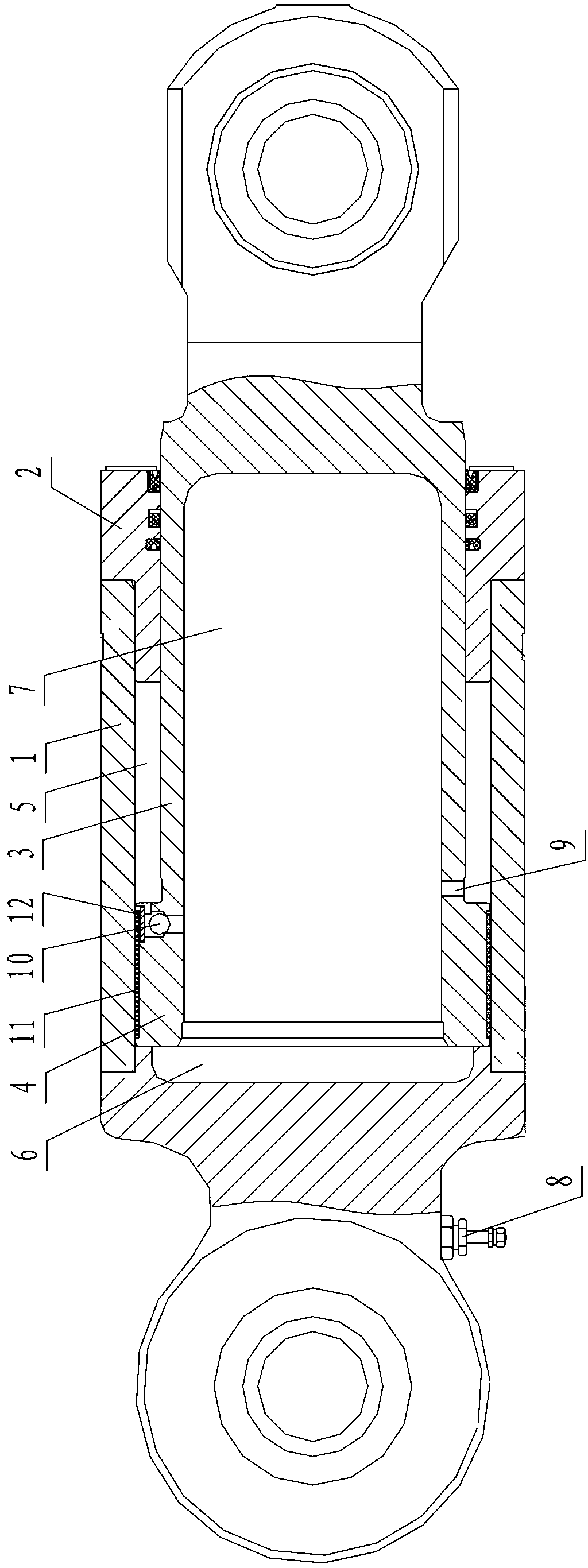
[0011] Such as figure 1 The shown rear suspension oil cylinder for a heavy industrial and mining vehicle is installed at the rear of the vehicle to support the upper and lower frames. It includes a cylinder body 1 with an open front end and a closed rear end, a guide sleeve 2 installed at the front end opening of the cylinder body 1, a piston rod 3, and a piston 4 located at the rear end of the piston rod 3 and integrally structured with the piston rod 3, wherein the cylinder The body 1 is welded and combined by the rear cover and the cylinder body, the piston rod 3 is in fluid-tight sliding fit with the guide sleeve 2, the piston 4 ...


PUM


Abstract

The invention discloses a rear suspension oil cylinder for a heavy-duty industrial mining vehicle. The rear suspension oil cylinder is arranged at the rear part of a vehicle and used for supporting an upper vehicle frame and a lower vehicle frame and comprises a cylinder body, a guide sleeve arranged at the front end of the cylinder body, a piston rod and a piston, wherein the piston rod is in sliding fit with the guide sleeve, the piston is in sliding fit with the inner wall of the cylinder body, the cylinder body is partitioned into a rod cavity and a rodless cavity of the oil cylinder by the piston, the piston is positioned at the tail end of the piston rod, the piston and the piston rod are of an integral structure, the piston rod is provided with an inner cavity which is communicated with the rodless cavity, one end of the inner cavity is closed, an inflation valve for injecting oil and inflating air to the rodless cavity is arranged at the tail part of the cylinder body, and the piston rod is respectively and radially provided with a damping hole for communicating the inner cavity and the rod cavity and a steel ball which pushes unidirectionally against the rod cavity from the inner cavity. The rear suspension oil cylinder can be suitable for different pavement situations by making reciprocated up-down movement in the traveling process of the vehicle, and achieves the functions of shock absorption and support; and the alternate change of the damping forces can be realized in the traveling process of the vehicle due to adoption of the damping hole and the steel ball which pushes unidirectionally against, therefore the purpose of ensuring the movement stability of the vehicle is achieved.

Description

technical field [0001] The invention relates to the technical field of hydraulic cylinders, in particular to a rear suspension cylinder for heavy industrial and mining vehicles. Background technique [0002] Heavy-duty industrial and mining vehicles have a large load and often run under poor road conditions. Therefore, people expect them to have good driving stability, cushioning reliability and ride comfort. These indicators are related to the inherent vibration characteristics of the body, and the body The natural vibration characteristics of a car are determined by its suspension system. Most of the traditional suspension systems are composed of shock absorbers and coil springs or leaf springs. Since the stiffness of the springs is a fixed value, in order to meet the requirements, when the stiffness of the suspension is required to be soft, the space for the suspension is large. The mass is too large to adapt to the lightweight development of heavy-duty chassis, and it c...

Claims


Application Information

Patent Timeline
Patent Type & Authority Applications(China)
IPC IPC(8): F16F9/06
Inventor 汪立平兰根招
Owner JIANGSU HENGLI HYDRAULIC
Learn More