Fluidized bed deacidification purification device and process

A purification device and fluidized bed technology, which is applied in the direction of silicon oxide, silicon dioxide, etc., can solve the problems affecting the normal operation of the equipment and the deacidification effect, reduce the service life of the equipment, and the deacidification effect is unstable, so as to achieve good deacidification Purification effect, device cost saving, height reduction effect

Active Publication Date: 2013-03-27
赤峰盛森硅业科技发展有限公司
View PDF4 Cites 6 Cited by
  • Summary
  • Abstract
  • Description
  • Claims
  • Application Information

AI Technical Summary

Problems solved by technology

[0003] For a long time, the gas phase SiO 2 The deacidification purification technology has been stuck in the technology of vertical fluidized bed electric heating to remove surface HCl. Due to the fact that the height of the vertical deacidification furnace should not be too high, the deacidification capacity of the equipment is limited, the deacidification effect has been unstable, and the deacidification uneven acid
However, the traditional electric heating method not only wastes energy, but also uses external heating to cause great damage to the equipment. This deacidification method poses a challenge to the material of the equipment.
In recent years, there has been an internal heating technology of opening holes on the cylinder of the deacidification furnace to install quartz glass tubes (the quartz glass tubes are equipped with electric furnace wires). Frequent replacement reduces the service life of the equipment, and the replacement of the electric heating tube affects the normal operation and deacidification effect of the equipment, and fails to better solve the problem of SiO in the gas phase method. 2 deacidification problem

Method used


Image

  • Fluidized bed deacidification purification device and process
  • Fluidized bed deacidification purification device and process

Examples


Embodiment 1

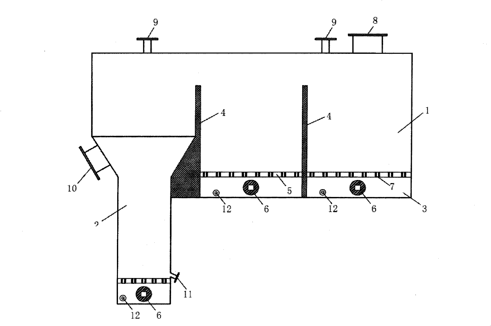
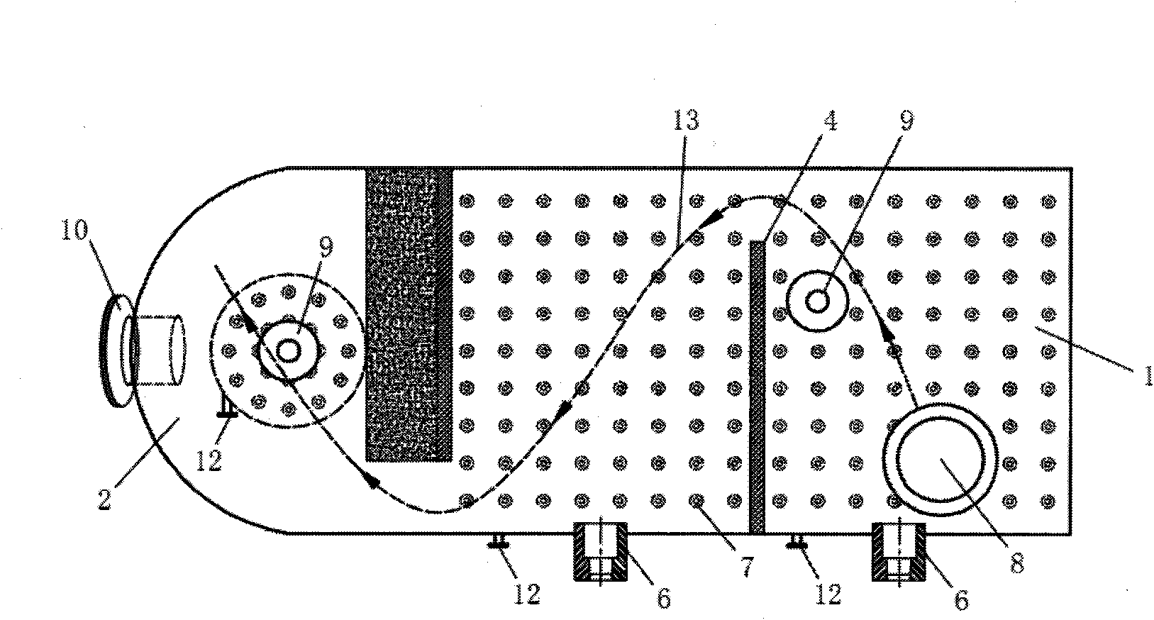
[0025] like figure 1 , figure 2 As shown, the fluidized bed deacidification purification device is generally divided into two parts: horizontal fluidized bed 1 and vertical fluidized bed 2, and each part is divided into upper and lower layers. It is a combustion chamber 3 for hydrogen and air. There is a burner 6 in the combustion chamber 3. The upper and lower layers are separated by a partition 5. There are gas channels 7 on the partition 5. The gas channels 7 can be evenly distributed on the partition 5. The upper layer of the type fluidized bed is divided into several chambers by a number of baffles 4, and there are communication channels between the chambers, so that the material can flow from the feeding chamber to the rear chambers in sequence until the material enters the vertical fluidized bed. The fluidized bed is discharged from the outlet 10 of the self-supporting fluidized bed.

[0026] The passages between the inner chambers of the horizontal fluidized bed 1 a...


PUM


Abstract

The invention discloses a fluidized bed deacidification purification device and process, and belongs to the field of inorganic fine chemical engineering. The device is generally divided into a horizontal fluidized bed part and a vertical fluidized bed part, wherein each part is divided into an upper layer and a lower layer; each upper layer is a fluidized bed part for conveying materials; each lower layer is a combustion chamber of hydrogen and air; each combustion chamber is internally provided with a combustor; the upper layers and the lower layers are separated by partition plates; each partition plate is provided with a gas channel; the upper layer of the horizontal fluidized bed is separated into a plurality of chambers by a plurality of baffles; through channels are formed among the chambers, so that the materials can pass through from a feeding chamber to the following chambers sequentially until the materials flow into the vertical fluidized bed and are discharged from a discharge port of the vertical fluidized bed; and a vapor-phase silicon dioxide material after being deacidified by the horizontal fluidized bed enters the vertical fluidized bed for deacidification. Compared with the prior art, the deacidification technology disclosed by the invention enables the pH of white carbon black to be stabilized in a range from 4.3 to 4.6 by utilizing two-stage deacidification and improves product quality of SiO2 by using a vapor phase method.

Description

technical field [0001] The invention belongs to the field of inorganic fine chemical industry, and specifically relates to a deacidification and purification device for nano powder materials, in particular to a gas-phase method SiO 2 Deacidification purification device and process. Background technique [0002] Gas Phase Combustion Synthesis of SiO by Gas Phase Process 2 Widely used in silicone rubber, adhesives and other fields, gas phase SiO 2 During the preparation process of gas phase combustion, a large amount of HCl is adsorbed, and HCl is removed to become gas phase SiO 2 An important process of preparation, the fluidized bed is gradually applied to the gas phase process SiO due to the advantages of uniform temperature, high heat transfer and mass transfer rate between gas and solid. 2 Surface HCl removal and surface treatment. [0003] For a long time, the gas phase SiO 2 The deacidification purification technology has been stuck in the technology of vertical fl...

Claims


Application Information

Patent Timeline
Patent Type & Authority Applications(China)
IPC IPC(8): C01B33/12
Inventor 马公林艾俊峰赵春宇
Owner 赤峰盛森硅业科技发展有限公司
Why Eureka
Try Eureka