
Yarn Cutting Suction Device and Spinning Winding Device

The technology of a suction device and a winding device is applied in the directions of transportation and packaging, transportation of filamentous materials, and processing of thin materials.

Active Publication Date: 2017-03-01
TMT MACHINERY INC
View PDF5 Cites 0 Cited by
  • Summary
  • Abstract
  • Description
  • Claims
  • Application Information

AI Technical Summary

Problems solved by technology

In this way, there is a need to reliably cut off a plurality of high-speed running threads with a cutter, and to suck and hold the cut threads with a suction gun during the transfer operation. very difficult homework

Method used


Image

  • Yarn Cutting Suction Device and Spinning Winding Device
  • Yarn Cutting Suction Device and Spinning Winding Device
  • Yarn Cutting Suction Device and Spinning Winding Device

Examples


Embodiment 1

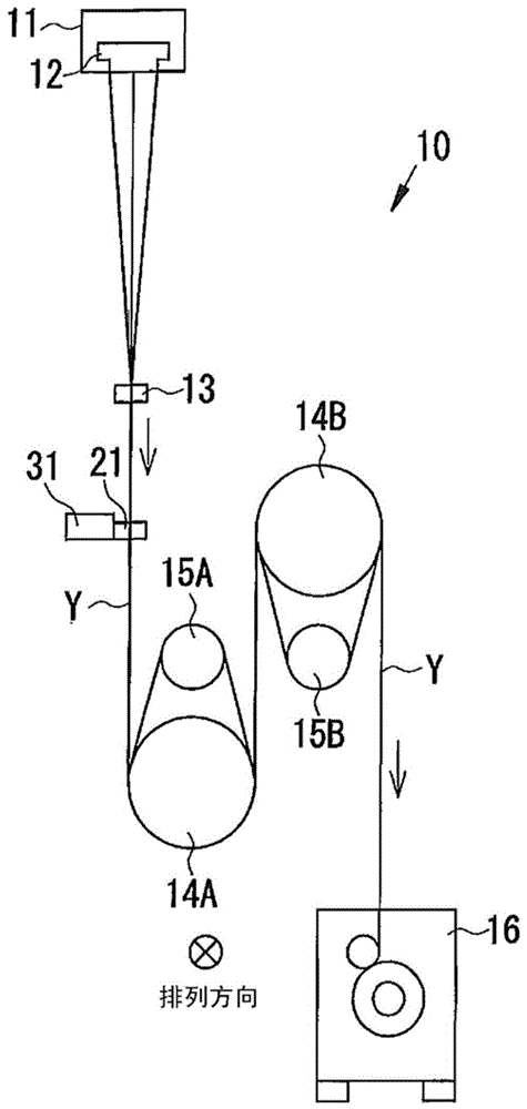
[0032] use Figure 1 to Figure 6 The spinning winding device 10 of Example 1 of the present invention will be described. Such as figure 1 As shown, the spinning and winding device 10 mainly includes a spinning device 11, an oil supply nozzle 13, a yarn path restricting guide 21, a yarn cutting and sucking device 31, godet rollers 14A, 14B, a yarn winding device 16, and a control unit 18. . The fiber spun by the spinning device 11 travels toward the yarn winding device 16, undergoes various processes on the way to form a yarn Y, and is wound up as a package. In the following description, fibers and threads are not distinguished, and they are only described as threads. Further, the upstream side and the downstream side in the direction in which the fiber (yarn Y) travels from the spinning device 11 to the yarn winding device 16 will be described as the upstream side and the downstream side in the traveling direction of the yarn Y, respectively.

[0033] The spinning device 1...

Embodiment 2

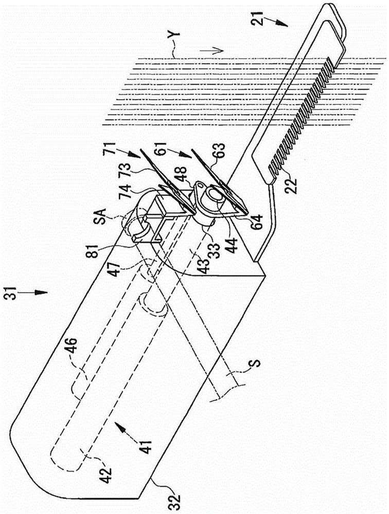
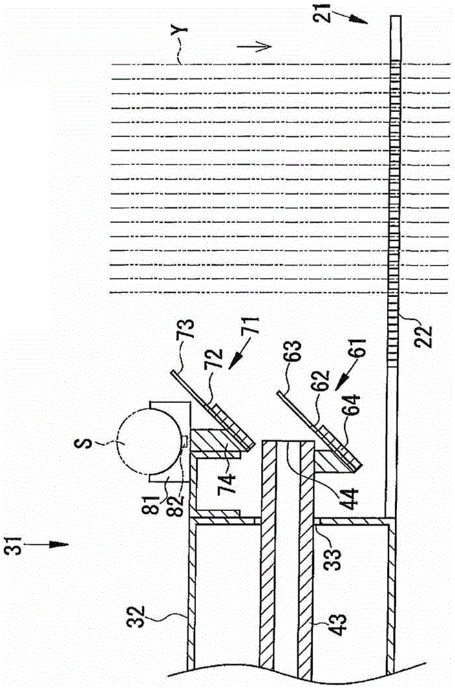
[0063] then use Figure 7 to Figure 11 The spinning winding device 10 of Example 2 of the present invention will be described. Embodiment 2 is similar to Embodiment 2 in that the suction part 44 of the thread cutting suction device 31 and the first cutter 61 are fixed, and that the plurality of threads Y are moved to the side of the first cutter 61 by the wire pulling guide 60 . 1 is quite different from the thread cutting suction device 31. Since the configuration other than the thread cutting and suction device 31 is the same as that of the first embodiment, the thread cutting and suction device 31 will be mainly described.

[0064] Such as Figure 7 , Figure 8 , Figure 9 As shown, the thread cutting suction device 31 mainly includes a suction device 41 , a wire pulling guide 91 , a first cutter 61 , a second cutter 71 , and a positioning unit 81 .

[0065] The suction device 41 is a device that suctions the plurality of yarns Y cut by the first cutter 61 . The sucti...


PUM


Abstract

The present invention provides a yarn cutting and suction device that does not require skill and allows anyone to easily perform a transfer operation, which is a very difficult operation that requires skill on the part of the operator. A thread cutting and suction device (10) that cuts and attracts multiple threads (Y) running in one direction. It is provided with a first cutter (61) that cuts the multiple threads (Y) and attracts the first cutter. The suction part (44) is arranged on the upstream side of the suction part (44) and cuts the plurality of filaments (Y) suctioned by the suction part (44). 2 cutters (71).

Description

technical field [0001] The present invention relates to the technology of a yarn cutting and suction device and a spinning winding device. Background technique [0002] Conventionally, a spinning winding device is known in which fibers spun from a spinning device are bundled to form a plurality of yarns, the yarns are subjected to processing such as stretching, and then wound to form a plurality of packages. In addition, a yarn cutting and suction device arranged downstream of the spinning device is also known (see, for example, Patent Document 1). [0003] The yarn cutting and suction device cuts all the yarns and sucks and holds the yarns continuously spun from the spinning device when the spinning winding device malfunctions or an abnormality such as yarn breakage occurs. As a result, the continuously spun yarn is prevented from being entangled on the downstream rotating body or the shape of the package is out of shape. [0004] However, when the failure of the spinning...

Claims


Application Information

Patent Timeline
Patent Type & Authority Patents(China)
IPC IPC(8): B65H63/04
CPCB65H54/71B65H54/88B65H57/16B65H2701/3132D01D7/00
Inventor 桥本欣三岸根章典
Owner TMT MACHINERY INC
Learn More