
Method and device for resource distribution

A resource allocation and resource technology, applied in the field of resource allocation of wireless resources, can solve the problems of large amount of SDU data, easy damage to SDU integrity, affecting the overall performance of LTE, etc., to protect integrity, reduce overhead and be retransmitted possibility, the effect of reducing overhead

Inactive Publication Date: 2013-03-20
이노피데이인코포레이티드 +1
View PDF3 Cites 9 Cited by
  • Summary
  • Abstract
  • Description
  • Claims
  • Application Information

AI Technical Summary

Problems solved by technology

[0005] This application provides a resource allocation method and device for wireless resources to solve the problem that the existing scheduler resource allocation and scheduling schemes are easy to destroy the integrity of the SDU, so that the amount of transmitted SDU data is relatively large, which affects the overall performance of LTE

Method used


Image

  • Method and device for resource distribution
  • Method and device for resource distribution
  • Method and device for resource distribution

Examples


Embodiment 1

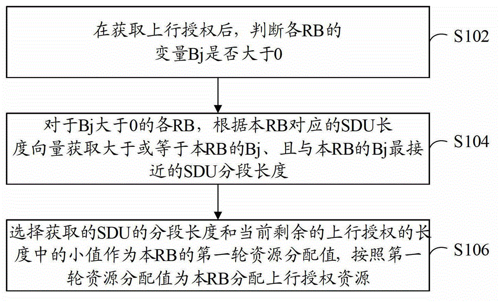
[0029] refer to figure 1 , shows a flowchart of steps of a resource allocation method according to Embodiment 1 of the present application.

[0030] The resource allocation method in this embodiment includes the following steps:

[0031] Step S102: After obtaining the uplink grant, determine whether the variable Bj of each RB is greater than 0.

[0032] Bj is used to identify the length of radio resources that need to be allocated to the RB. Bj is the product of the RB's PBR (Prioritised Bit Rate, guaranteed rate) and TTI (Transmission Time Interval, transmission time interval) when the RB is not authorized, indicating the data length that needs to be allocated to the RB in the first round during the current scheduling. Bj will gradually grow over time. After allocating resources for RB, Bj will be updated, and the resource value allocated for this RB will be subtracted from the original Bj, and Bj can be a negative value.

[0033] Step S104: For each RB with Bj greater th...

Embodiment 2

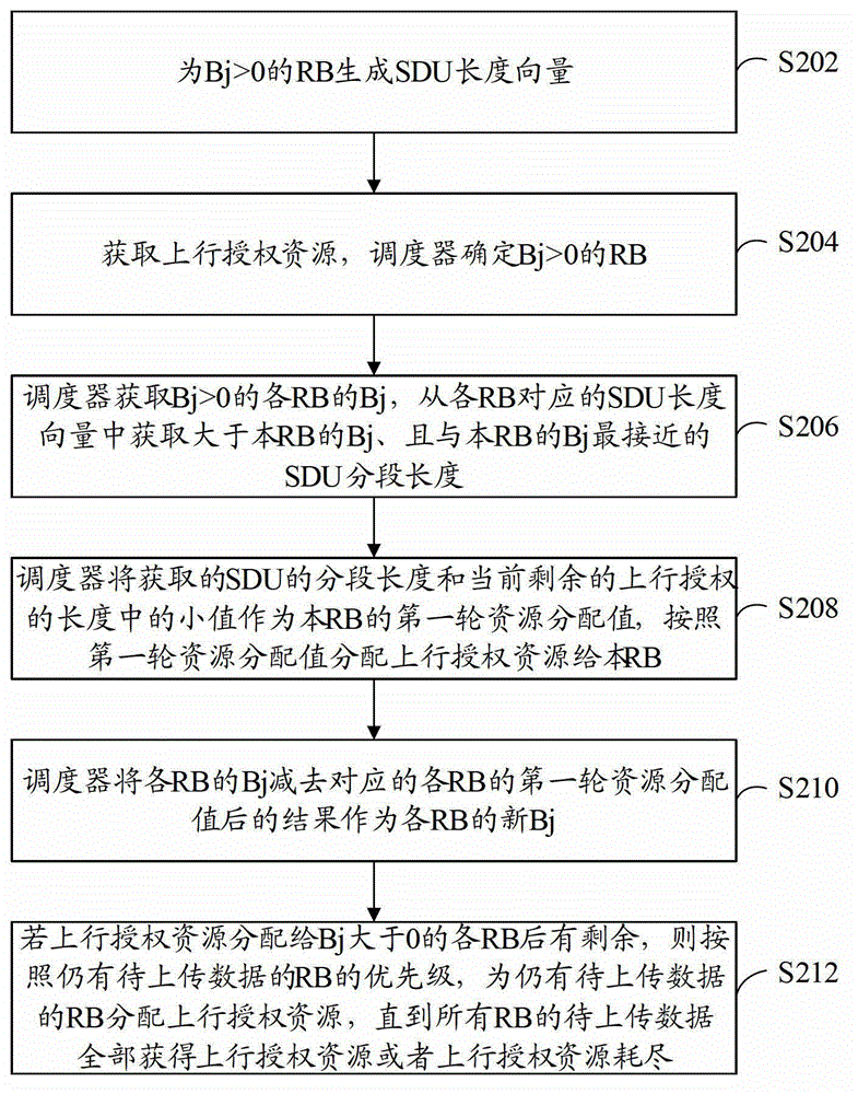
[0041] refer to figure 2 , shows a flowchart of steps of a resource allocation method according to Embodiment 2 of the present application.

[0042] The resource allocation scheme in this embodiment is based on the basic framework of two rounds of scheduling. The first round of scheduling is aimed at the PBR result Bj. For RBs with Bj>0, the ULgrant resources are allocated according to the priority order of the RBs according to the Bj result and the SDU length vector. For each RB; the specific scheduling scheme can refer to the above figure 1 Description of the examples shown. If each channel is satisfied before the ULgrant resources are exhausted, the second round of scheduling can be entered; the second round of scheduling will allocate the remaining ULgrant resources to the RBs that still have data to be sent in order according to the priority order of the RBs .

[0043] The resource allocation method in this embodiment includes the following steps:

[0044] Step S202:...

Embodiment 3

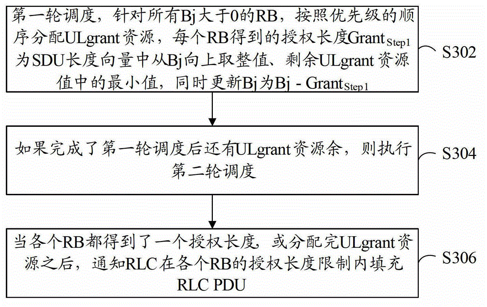
[0066] refer to image 3 , shows a flowchart of steps of a resource allocation method according to Embodiment 3 of the present application.

[0067] This embodiment still uses the basic framework based on two-round scheduling, and introduces the resource allocation method of this embodiment from the level of two-round scheduling. It should be explained first that whether two-round scheduling is required can be determined in the following way:

[0068] Th Step 1 = ∑ n = 0 N - 1 min ( L Total 1 ( n ) , Bj ( n ) ) ...


PUM


Abstract

The invention provides a method and a device for resource distribution. The method for resource distribution comprises that after uplink authorization is acquired, whether the variable Bj of each radio bear (RB) is larger than zero is judged, wherein the Bj of each RB is used for identifying the length of the radio resources which need to be distributed to the RB; if the Bj of each RB is larger than zero, business data unit fractional length which is larger than or equal to the Bj of each RB and is the most close to the Bj of each RB is acquired according to a business data unit length vector corresponding to each RB, wherein elements in the business data unit length vector is used for identifying the fractional length of each business data unit of each RB; a small value of the acquired fractional length of each business data unit and the length of current residual uplink authorization resources is chosen to be a first round of resource distribution value of each RB; the uplink authorization resources is distributed to each RB according to the first round of resource distribution value. According to the method and the device for resource distribution, segmentation of a signal distribution unit (SDU) can be effectively lowered, cost of uplink message is reduced, and the probability of retransmission is lowered.

Description

technical field [0001] The present application relates to the field of communication technologies, and in particular to a method and device for allocating wireless resources. Background technique [0002] In the LTE (Long Time Evolution, long-term evolution) system, a variety of terminal data services show their own unique performance requirements, such as the most typical web pages requiring low response time, FTP (File Transfer Protocol, file transfer protocol) services require data The correctness of the audio and video services, as well as the guaranteed rate requirements. The allocation and competition of these different service data for radio resources will be concentrated in the "multi-RB (Radio Bearer, radio bearer) scheduler" of the MAC (Medium Access Control, medium access control) layer in the LTE system. Because the MAC layer can be understood as the interface between the physical layer and the service layer on the data plane, the MAC layer stores the data block...

Claims


Application Information

Patent Timeline
Patent Type & Authority Applications(China)
IPC IPC(8): H04W72/04H04L5/00
Inventor 周光明朱文博钟展辉蒋诗梅
Owner 이노피데이인코포레이티드
Learn More