Eureka AIR delivers breakthrough ideas for toughest innovation challenges, trusted by R&D personnel around the world.

Manufacturing method and structure of solar battery

A manufacturing method and battery technology, applied in the field of solar cells, can solve the problems of decreased electrical conductivity and increased series resistance of the battery, etc., and achieve the effects of improving photo-induced stability, solving mutual contradictions, and improving photoelectric conversion efficiency.

Inactive Publication Date: 2013-03-06
ZHEJIANG ASTRONERGY
View PDF4 Cites 3 Cited by
  • Summary
  • Abstract
  • Description
  • Claims
  • Application Information

AI Technical Summary

Problems solved by technology

[0007] On the other hand, the contradiction between the optical bandgap and the conductivity of the amorphous silicon oxygen P-type doped layer is a bottleneck that limits its scale application: the higher the oxygen content, the wider the optical bandgap of the material; but the conductivity Decrease, mainly manifested as a significant increase in the series resistance of the battery

Method used


Image

  • Manufacturing method and structure of solar battery
  • Manufacturing method and structure of solar battery
  • Manufacturing method and structure of solar battery

Examples


Embodiment Construction

[0044] The following disclosure provides many different embodiments or examples for implementing different structures of the present invention. To simplify the disclosure of the present invention, components and arrangements of specific examples are described below. Of course, they are only examples and are not intended to limit the invention. Furthermore, the present invention may repeat reference numerals and / or letters in different instances. This repetition is for the purpose of simplicity and clarity and does not in itself indicate a relationship between the various embodiments and / or arrangements discussed. In addition, various specific process and material examples are provided herein, but one of ordinary skill in the art will recognize the applicability of other processes and / or the use of other materials. Additionally, configurations described below in which a first feature is "on" a second feature may include embodiments where the first and second features are form...


PUM


Abstract

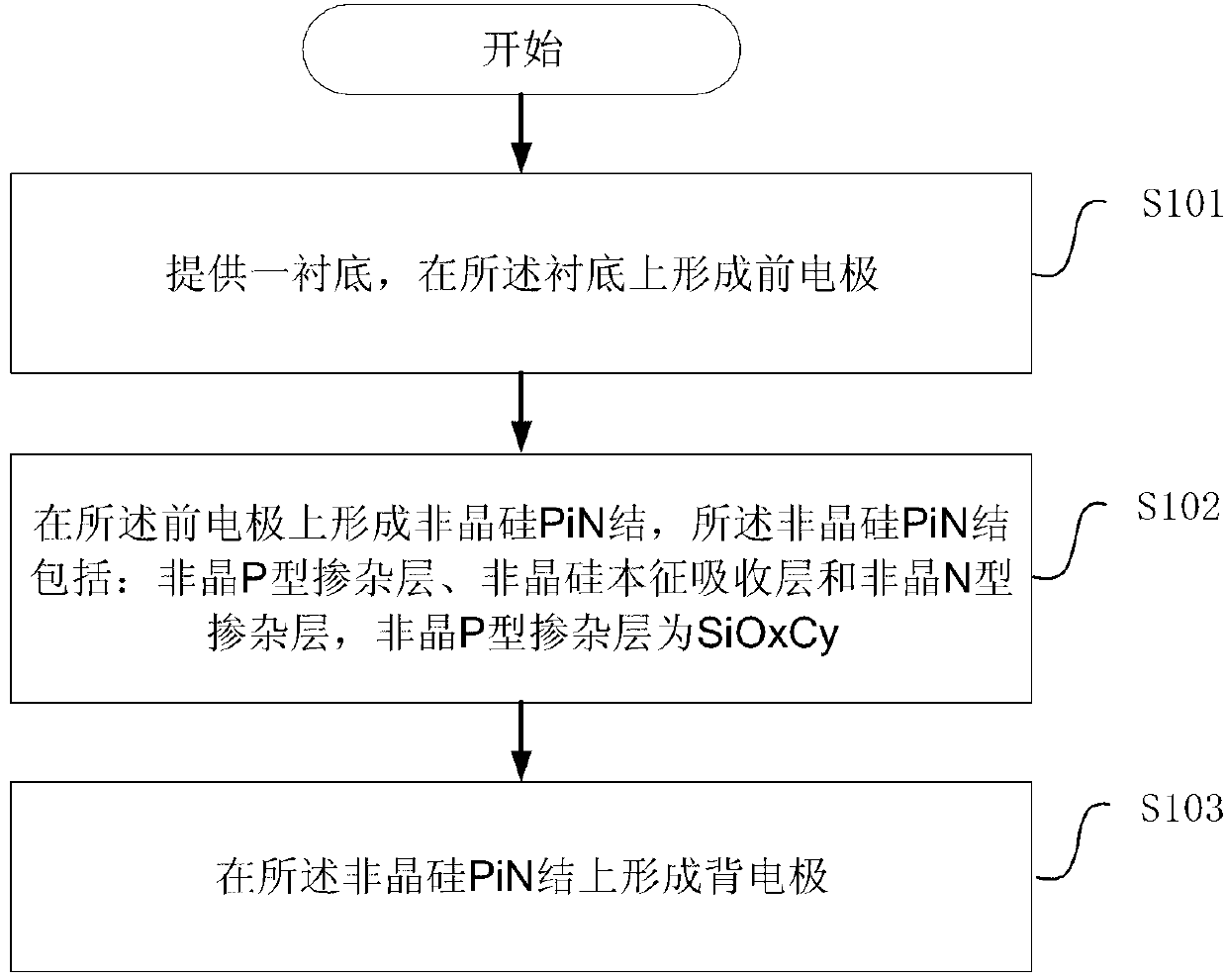
The invention discloses a manufacturing method of a solar battery. In According to the manufacturing method, a C-O (Carbohydrate Oxidation) codoping method is adopted to prepare an amorphous p-type doped layer of an amorphous silicon roof cell of a silicon thin-film solar battery such as an amorphous silicon unijunction thin-film battery, and an amorphous silicon / amorphous silicon-germanium or amorphous silicon / microcrystalline silicon battery. Correspondingly, the invention further provides a solar battery structure formed through the manufacturing method disclosed by the invention. The manufacturing method and the solar battery structure can effectively eliminate the contradiction so far existing between the optical band gap and electric conduction property of the amorphous p-type doped layer prepared by silica, and the stability and the photoelectric conversion efficiency of the solar battery are improved.

Description

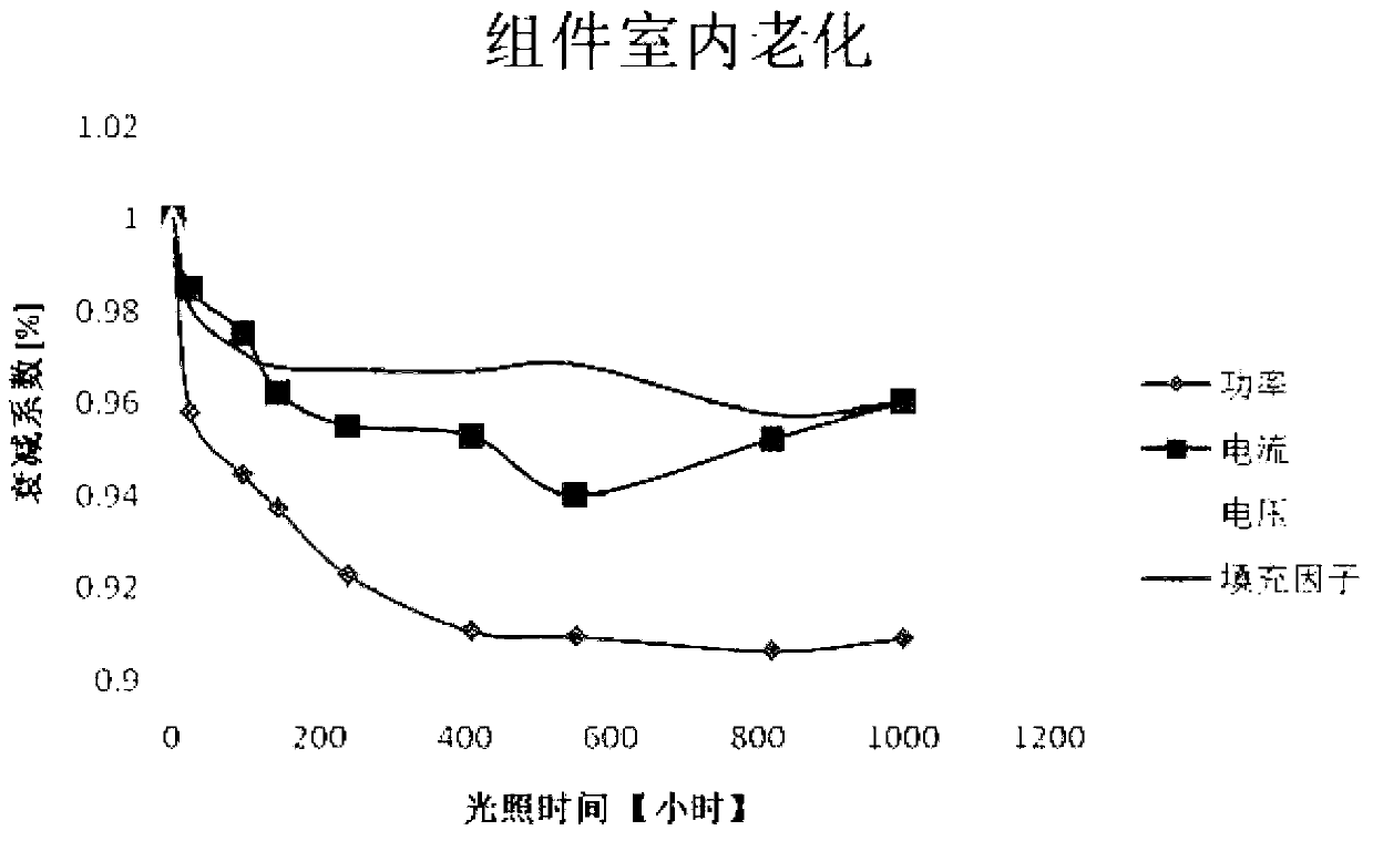
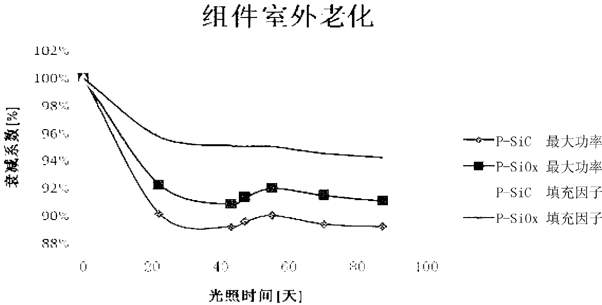
technical field [0001] The invention relates to the technical field of solar cells, in particular to a manufacturing method and structure of the solar cell. Background technique [0002] The inherent S-W (Steabler-Wronski, light-induced degradation) effect of amorphous silicon itself is the main reason for the light-induced degradation of silicon-based thin film components. refer to figure 1 , figure 1 It is the indoor light-induced attenuation curve of a typical amorphous silicon / microcrystalline silicon laminated solar module. From figure 1 It can be seen from the figure that when the light intensity in the control room is 1000W / m 2 , Indoor light-induced attenuation of amorphous silicon / microcrystalline silicon stacked cell components (1100mm×1300mm) when the component surface temperature is 50±2°C. [0003] At present, the light-induced attenuation coefficient of the industrialized amorphous silicon single-junction module is in the range of 15%~20%, and the light-in...

Claims


Application Information

Patent Timeline
IPC IPC(8): H01L31/20H01L31/075H01L31/0288H01L31/076
CPCY02E10/50Y02B10/12Y02B10/10Y02E10/548Y02P70/50
Inventor 郁操牛新伟陈晨
Owner ZHEJIANG ASTRONERGY
Why Eureka
Eureka Blog
Learn More