Ion implanter

An ion implantation equipment, ion beam technology, applied in the direction of ion implantation plating, coating, electrical components, etc., can solve problems such as less expectations, and achieve the effect of reducing expansion and contraction

Inactive Publication Date: 2013-03-06
NISSIN ION EQUIP CO LTD
View PDF6 Cites 8 Cited by
  • Summary
  • Abstract
  • Description
  • Claims
  • Application Information

AI Technical Summary

Problems solved by technology

However, if the size of the device is too large, a wide location for arranging the large device is required in the semiconductor factory, which is less desirable in view of the relationship with the arrangement positions of other devices

Method used


Image

  • Ion implanter
  • Ion implanter
  • Ion implanter

Examples


Embodiment Construction

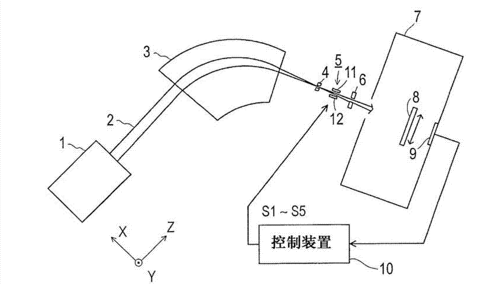
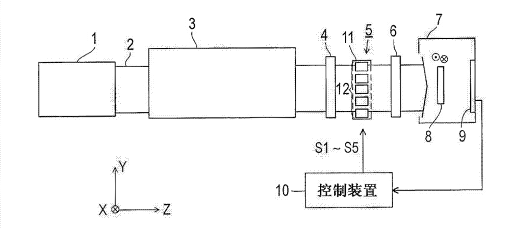
[0035] Fig. 1 shows an example of an ion implantation apparatus according to the present invention. When cut in a plane perpendicular to the traveling direction of the ion beam, the ribbon ion beam of the present invention has a substantially rectangular cross section or a substantially elliptical cross section. The cross-section of the ion beam may be rectangular, oblong, or circular. In this embodiment, the Z direction refers to the traveling direction of the ribbon ion beam, the Y direction refers to the long side direction of the ribbon ion beam, and the X direction refers to the short side direction of the ribbon ion beam. Also, when the ion beam has an oblong cross-section, the Y direction may refer to the long axis direction of the ion beam and the X direction may refer to the short axis direction of the ion beam. In addition, the ion beam processed in the present invention is an ion beam having a positive charge.

[0036] Figure 1A The state of the ion implantation devi...


PUM


Abstract

The invention provides an ion implanter including a deflecting electrode and a shield member. The ion beam has a ribbon shape. The deflecting electrode deflects at least a part of the ion beam in a long side direction toward a short side direction of the ion beam, based on a result measured of a beam current density distribution in the long side direction. The shield member partially shields the ion beam deflected by the deflecting electrode. The deflecting electrode includes a plate electrode and an electrode group including plural electrodes. The electrode group is disposed to face the plate electrode to interpose the ion beam between the plate electrode and the electrode group. The plate electrode is electrically grounded, and the plurality of electrodes are electrically independent from each other. Each of the plurality of electrodes is connected to an independent power source from other power sources to perform a potential setting.

Description

Technical field [0001] The present invention relates to an ion implantation device including an electric field lens. The ion implantation device adjusts the current density distribution in the length direction of a ribbon ion beam elongated in one direction. Background technique [0002] In order to cope with the increase in the size of the substrate, the ion implantation apparatus uses a ribbon-shaped ion beam elongated in one direction. When cut in a plane perpendicular to the traveling direction of the ion beam, the ion beam has a substantially rectangular cross section. For example, the ion implantation device transports the substrate in the short-side direction of the ribbon ion beam substantially perpendicular to the length direction of the ribbon ion beam, and irradiates the ion beam on the entire surface of the substrate, thereby performing ion implantation to the substrate Of craftsmanship. [0003] In addition, in connection with the miniaturization of semiconductor dev...

Claims


Application Information

Patent Timeline
Patent Type & Authority Applications(China)
IPC IPC(8): H01J37/317
CPCH01J2237/30472H01J2237/31703H01J2237/0835H01J2237/30455H01J37/3171C23C14/48H01J37/304H01J37/12H01J37/147H01J37/317
Inventor 内藤胜男
Owner NISSIN ION EQUIP CO LTD
Why Eureka
Try Eureka