
Commutatorless high-temperature heat exchanger

A high-temperature heat exchanger without reversing technology, which is applied in the field of industrial furnaces, can solve problems such as furnace pressure fluctuations, increased operating risks for operators, and failure of the combustion system to achieve continuous operation in a hot state and heat exchange. Heat exchange efficiency and the effect of preventing hot gas from leaking out

Inactive Publication Date: 2013-03-06
苏州有色金属研究院有限公司 +2
View PDF6 Cites 2 Cited by
  • Summary
  • Abstract
  • Description
  • Claims
  • Application Information

AI Technical Summary

Problems solved by technology

This has not only caused unnecessary waste of fuel, but also increased the labor intensity of workers.
In the traditional reversing technology, the burners work in pairs, and each burner burns and exhausts alternately, which will inevitably cause fluctuations in furnace pressure, frequent phase changes, easy damage to the regulating valve, and failure alarms caused by unsuccessful ignition.
The failure of the combustion system caused by the failure of the reversing equipment directly affects the production, and there are certain safety hazards
For the intermittent reversing burner, the investment in the reversing part is increased. At the same time, if gas is used as fuel, the reversing of the combustion system also increases the operational risk of the operator. To solve this problem, considerable funds must be invested

Method used


Image

  • Commutatorless high-temperature heat exchanger
  • Commutatorless high-temperature heat exchanger

Examples


Embodiment Construction

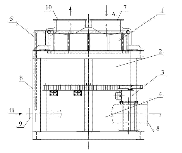
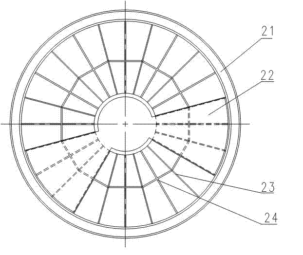
[0016] Such as figure 1 As shown, a non-reversing high-temperature heat exchanger includes a frame 6, a heat storage device and a driving mechanism 3. The heat storage device is in a cylindrical structure and includes a lower cylinder 4, a rotor heat storage body 2 and an upper cylinder arranged in sequence. body 1, the lower cylinder body 4 is fixed on the frame 6, the interior of the lower cylinder body is divided into a low-temperature air chamber and a low-temperature flue gas chamber, and the side of the lower cylinder body is provided with a low-temperature air inlet 9 and a low-temperature flue gas outlet 8; the rotor heat storage body 2 Rotatably supported on the lower cylinder body 4, the rotor heat storage body 2 is filled with heat storage medium; the upper cylinder body 1 is located on the rotor heat storage body and fixed on the frame, and the upper cylinder body is divided into a high-temperature flue gas chamber and a high-temperature Air cavity, the top of the ...


PUM


Abstract

The invention relates to a commutatorless high-temperature heat exchanger. A heat storage device comprises a lower cylinder, a rotor heat storage body and an upper cylinder which are arranged in sequence, wherein the lower cylinder is fixedly arranged on a framework; the lower cylinder is partitioned into a low-temperature air chamber and a low-temperature gas chamber; a side face of the lower cylinder is provided with a low-temperature air inlet and a low-temperature gas outlet; the rotor heat storage body is supported against the lower cylinder in a free rotation manner and is filled with a heat storage medium; the upper cylinder is positioned on the rotor heat storage body and is fixedly arranged on the framework; the upper cylinder is partitioned into a high-temperature gas chamber and a high-temperature air chamber; the top of the upper cylinder is provided with a high-temperature gas inlet and a high-temperature air outlet; the high-temperature gas inlet in the upper cylinder is communicated with the low-temperature gas outlet in the lower cylinder; the low-temperature air inlet in the lower cylinder is communicated with the high-temperature air outlet in the upper cylinder; and a driving mechanism on the framework is in drive connection with the rotor heat storage body to drive the rotor heat storage body to rotate. The high-temperature gas heat is continuously transferred to combustion-supporting air by the rotation of the rotor heat storage body, so that thermal-state continuous operation and heat exchange are realized, and the heat exchange efficiency is high.

Description

technical field [0001] The invention relates to a non-reversing high-temperature heat exchanger, which is used for industrial kilns where hot water or steam is not used to recover heat. Background technique [0002] Regenerative high-temperature air combustion technology (HTAC) is a new concept of combustion technology that emerged in the late 1980s. It combines waste heat recovery with high-efficiency combustion and reduction of NO x Emissions and other technologies are organically combined to achieve energy saving and reduction of NO x Dual goals for emissions. With the advancement of equipment and materials, regenerative heat exchange technology has been widely used in heating furnaces and ladle bakers in metallurgical enterprises. However, while the technology holds great energy-saving potential, it also has some problems of its own. [0003] For example, in the non-ferrous metallurgy industry, the temperature in the furnace varies greatly due to its process character...

Claims


Application Information

Patent Timeline
Patent Type & Authority Applications(China)
IPC IPC(8): F27D17/00F23L15/00
CPCY02E20/34Y02P10/25
Inventor 李浩谢晓燕路振龙杨志敏贵广臣李世轩兰田王峥嵘刘正春
Owner 苏州有色金属研究院有限公司
Learn More