High-temperature synthetic gas chilling device and high-temperature synthetic gas chilling method for gasification furnace

A synthesis gas and gasification furnace technology, applied in the manufacture of combustible gas, petroleum industry, etc., can solve the problems of inability to ensure the uniform mixing of synthesis gas and cooling water, reduce the conversion efficiency of gasification, and reduce the temperature of gasification furnace. The nozzle burns out quickly, the effect of increasing the residence time and increasing the mixing intensity

Active Publication Date: 2013-03-06
HUAZHONG UNIV OF SCI & TECH +1
View PDF4 Cites 7 Cited by
  • Summary
  • Abstract
  • Description
  • Claims
  • Application Information

AI Technical Summary

Problems solved by technology

[0007] Aiming at the defects of the prior art, the purpose of the present invention is to provide a gasifier high-temperature syngas quenching device, aiming at solving the problem of lowering the temperature in the gasifier caused by injecting quenching water directly from the top of the gasifier in the prior art , Reduce gasification conversion efficiency and fail to ensure uniform mixing of syngas and cooling water, resulting in burnout of nozzles and shutdown of production

Method used


Image

  • High-temperature synthetic gas chilling device and high-temperature synthetic gas chilling method for gasification furnace
  • High-temperature synthetic gas chilling device and high-temperature synthetic gas chilling method for gasification furnace
  • High-temperature synthetic gas chilling device and high-temperature synthetic gas chilling method for gasification furnace

Examples


Embodiment Construction

[0027] In order to make the object, technical solution and advantages of the present invention clearer, the present invention will be further described in detail below in conjunction with the accompanying drawings and embodiments. It should be understood that the specific embodiments described here are only used to explain the present invention, not to limit the present invention.

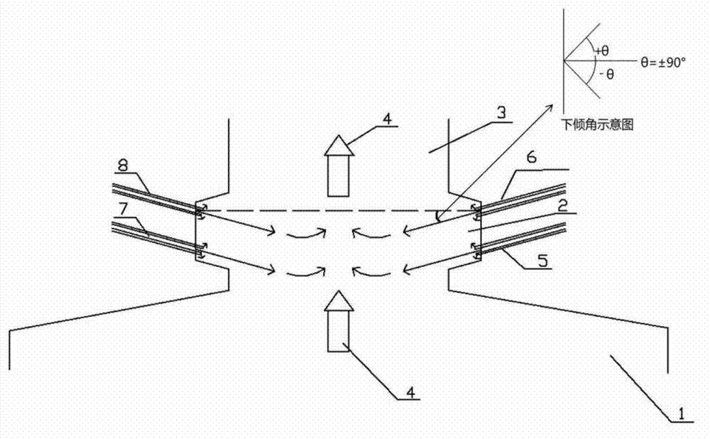
[0028] The invention adopts the spray quenching and gas injection protection modes arranged in a tangential circle, and can quench the high-temperature (1350-1650° C.) syngas at the outlet of the gasification furnace and solidify the slag through the adjustment of the amount of cooling water. The cooling load is large and the cooling gas consumption is small.

[0029] Such as figure 1 As shown, the syngas quenching device includes a coal gasifier 1, a quenching chamber 2, and a syngas conduit 3, wherein the quenching chamber 2 is a space formed by moving a circular, rectangular or polygonal sectio...


PUM


Abstract

The invention discloses a high-temperature synthetic gas chilling device and a high-temperature synthetic gas chilling method for a gasification furnace. The chilling device comprises the coal gasification furnace, a chilling chamber and a synthetic gas guide pipe, wherein the chilling chamber is a space formed in a mode that a round, rectangular or polygonal section moves along the normal direction of the section; multiple layers of sprayer units are distributed on the periphery of the chilling chamber; and each sprayer unit comprises multiple sprayers distributed in a tangential circle shape along the circumferential direction; when the synthetic gas generated by the coal gasification furnace enters into the chilling chamber through the synthetic gas guide pipe so as to be chilled, the sprayers spray a cooling medium along a direction opposite to the synthetic gas movement direction, so that the cooling medium and the synthetic gas are uniformly mixed. According to the device and the method, multiple layers of multiple sprayers distributed in a tangential circle shape along the circumferential direction are adopted for spraying the cooling medium along the direction opposite to the synthetic gas movement direction, so that the influence of the chilling boundary on the temperature of the gasification furnace is reduced; and the cooling medium is sprayed along the direction opposite to the synthetic gas movement direction, so that the mixing intensity is improved, the residual rotation momenta of the synthetic gas are reduced, the length of the outlet guide pipe of the chilling chamber of the gasification furnace is greatly shortened, and the cost is lowered.

Description

technical field [0001] The invention belongs to the technical field of dry coal powder or coal water slurry or biomass or petroleum coke gasification quenching process, and more specifically relates to a high-temperature syngas quenching device and method for a gasifier. Background technique [0002] The second-generation coal gasification technology, such as Texaco coal-water slurry gasification and Shell dry pulverized coal gasification, has many advantages such as wide adaptability to coal types, high gasification pressure, large production capacity, high gasification efficiency, and low pollution. Therefore, it It is the preferred technology for the development of modern coal chemical industry. [0003] The Texaco gasification process is one of the new coal gasification processes in the 1980s. It is a pressurized gasification technology developed by the American Texaco Company with coal-water slurry as raw material and liquid slag discharge entrained bed. Texaca gasifie...

Claims


Application Information

Patent Timeline
IPC IPC(8): C10J3/82C10J3/84
Inventor 傅培舫余波徐才福
Owner HUAZHONG UNIV OF SCI & TECH
Why Eureka
Try Eureka