
Cloth bag deduster and fan assembly

A bag filter and combined device technology, applied in the field of mechanical manufacturing and processing, can solve the problems of short service life of fans, high transportation costs, affecting dust removal efficiency, etc., and achieve the effects of prolonging service life, good corrosion resistance and good working environment.

Inactive Publication Date: 2013-03-06
JIANGSU CHANGJING ENVIRONMENTAL PROTECTION TECH
View PDF0 Cites 11 Cited by
  • Summary
  • Abstract
  • Description
  • Claims
  • Application Information

AI Technical Summary

Problems solved by technology

[0003] (1) This connection structure makes the fan work in a positive pressure environment. The fan is generally a C-type positive pressure fan. The dust in the external dust collection pipe first passes through the fan and then enters the bag filter. The working environment of the fan is not ideal, making The fan wears seriously, the bearing is easily damaged, and the service life of the fan is short; in addition, because the fan works under positive pressure, dust will be ejected from the gaps that are not tightly sealed, which is easy to leak dust, affects the dust removal efficiency, and will cause the external space of the fan to work. pollution, not environmentally friendly
[0004] (2) The shell of the bag filter in the combination device of the bag filter and the fan is a box-type structure, which is welded. Once the shell is made, it cannot be disassembled, and it is also transported as a whole during transportation. , due to the large volume of the shell, it is inconvenient to ship, and the transportation cost is high, which brings great inconvenience to transportation;
[0005] (3) The shell of the bag filter in the combination device of the bag filter and the fan is made of iron plate material, which is easy to rust and corrode, and has a short service life. After being made of iron plate, it needs to be done externally. Paint, the process of making paint is time-consuming and laborious, not environmentally friendly, and the overall quality is poor, the appearance is poor in uniformity, and it is not easy to clean

Method used


Image

  • Cloth bag deduster and fan assembly
  • Cloth bag deduster and fan assembly

Examples


Embodiment

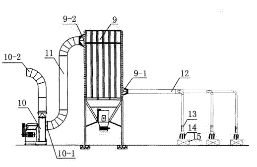
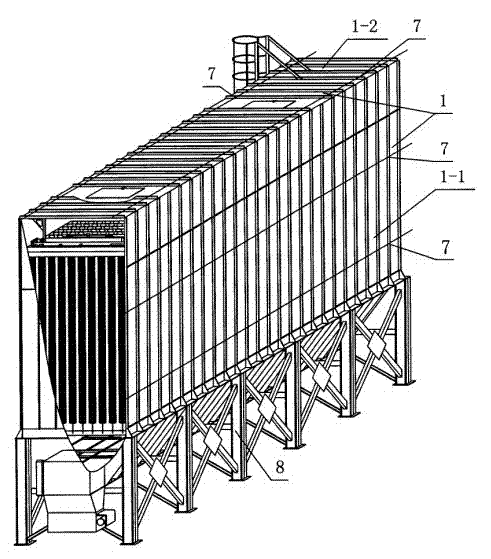
[0022] Such as figure 1 and figure 2 As shown, a combination device of a bag filter and a fan includes a bag filter 9 and a fan 10 , and also includes an air duct 11 . The bag filter 9 includes a housing 1, which is arranged on the frame 8, and the housing 1 is provided with a dust collector air inlet 9-1 and a dust collector air outlet 9-2. The fan 10 is provided with a fan air inlet 10-1 and a fan outlet 10-2. The air inlet 9-1 of the dust collector is directly connected with the external dust suction pipe 12, the air outlet 9-2 of the dust collector is connected with the air inlet 10-1 of the fan through the air pipe 11, and the air outlet 10-2 of the fan is connected with the external atmosphere. Fan 10 is an A-type negative pressure fan.

[0023] The housing 1 of the bag filter 9 is a modular structure, the housing 1 is composed of several side modules 1-1 and several upper modules 1-2 assembled, and the adjacent side modules 1-1 are fixed by fixed connectors 7 To be...


PUM


Abstract

The invention relates to a bag type dedusting device, and especially relates to a cloth bag deduster and fan assembly. The cloth bag deduster and fan assembly comprises a cloth bag deduster (9) and a fan (10), and also comprises an air duct (11), wherein the cloth bag deduster (9) comprises a housing (1); a deduster air inlet (9-1) and a deduster air outlet (9-2) are arranged on the housing (1); a fan air inlet (10-1) and a fan air outlet (10-2) are arranged on the fan (10); the deduster air inlet (9-1) is directly connected with an outside dust-absorbing pipeline (12); the deduster air outlet (9-2) is connected with the fan air inlet (10-1) through the air duct (11); and the fan air outlet (10-2) is connected with outside air. The cloth bag deduster and fan assembly has the advantages of simple structure, environmental protection, long fan service life, convenient dismounting, mounting and transportation of the cloth bag deduster, low transportation cost, high dedusting efficiency, and good dedusting effect.

Description

technical field [0001] The invention relates to a bag-type dedusting device, in particular to a combined device of a bag-type deduster and a fan. The invention is suitable for bag type dust removal equipment. The invention belongs to the technical field of mechanical manufacturing and processing. Background technique [0002] Bag-type dust removal equipment is suitable for the separation of dust from dust-containing gases in food, grain, medicine, building materials, chemicals and other industries. The material device is collected by the material collecting device and then discharged. The bag filter is a dry dust removal device suitable for capturing fine, dry, non-fibrous dust. The existing bag filter and fan combination device includes a bag filter and a fan, and also includes an air duct. The bag filter includes a casing, and the casing is provided with a dust collector air inlet and a dust collector air outlet. The fan is equipped with a fan inlet and a fan outlet, ...

Claims


Application Information

Patent Timeline
Patent Type & Authority Applications(China)
IPC IPC(8): B01D46/02B01D46/42
Inventor 沈鑫森
Owner JIANGSU CHANGJING ENVIRONMENTAL PROTECTION TECH
Learn More