Detonation control method of digital detonator

A digital detonator and control method technology, applied in the field of digital detonators, can solve the problems of poor supervision of detonators, detonators that cannot adapt to blasting accuracy and high blasting effect requirements

Inactive Publication Date: 2013-02-27
湖南长信畅中科技股份有限公司
View PDF4 Cites 14 Cited by
  • Summary
  • Abstract
  • Description
  • Claims
  • Application Information

AI Technical Summary

Problems solved by technology

[0004] The purpose of the present invention is to provide a digital detonator detonation control method with high blasting precision and high reliability of digital detonator supervision, so as to solve the problem that the existing detonator supervision is not effective and the fixed delay setting of the detonator cannot meet the requirements of high blasting accuracy and blasting effect. Occasionally Technical Issues

Method used


Image

  • Detonation control method of digital detonator
  • Detonation control method of digital detonator
  • Detonation control method of digital detonator

Examples


Embodiment 1

[0031] figure 1 It is a schematic diagram of the hardware connection of the digital detonator, detonator, data center and client in this embodiment. Depend on figure 1 It can be seen that the blasting client is connected to the data center, and the data center stores the number of digital detonators in reserve, the corresponding ID number, the number of the blasting operator, and fingerprint information. The blasting client is generally implemented by a computer, which can complete the communication in the data center, such as realizing the registration of operators and applying for blasting to the data center. The blasting client can also communicate with the detonator through usb or serial port. A detonator can also be connected with multiple digital detonators and manage and supervise the digital detonators, such as figure 2 As shown, preferably, a digital detonator connector can also be used to connect the detonator and multiple digital detonators together, so that the...

Embodiment 2

[0039] see figure 1 , Figure 5 , the detonation control method of the digital detonator of the present embodiment is carried out under the condition basically identical with the hardware condition of embodiment 1, and the difference between the two is that in the present embodiment, such as Figure 5 As shown, the blasting client is also connected to the fingerprint identification device. There are two types of fingerprint identification devices, one is embedded in the detonator to identify the fingerprint of the operator, and the other is an independent fingerprint collector used to register new blasters. After the registration is completed, the registration information is stored in the data center for convenience. Unified deployment.

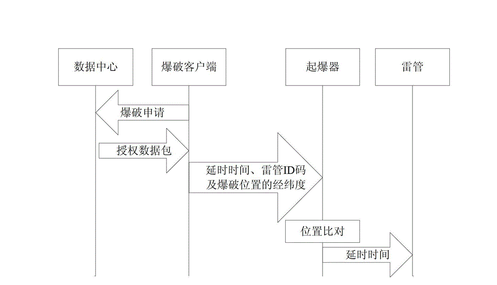
[0040] see Figure 4 , the detonation control method of the digital detonator of the present embodiment, comprises the following steps:

[0041] 1. Apply for blasting: The blasting client first shakes hands with the detonator and reads th...


PUM


Abstract

The invention discloses a detonation control method of a digital detonator. The detonation control method comprises the following steps of: launching detonation application to a data center, wherein the detonation application comprises the quantity of detonators and detonation positions; receiving and processing the detonation application through the data center, and generating an authorization data packet containing ID codes of the digital detonators and longitude and latitude corresponding to the detonation positions; acquiring the authorization data packet from the data center, and setting delay time of a digital detonator corresponding to the ID code of each digital detonator; downloading the delay time, the ID codes of the digital detonators and the detonation positions into a detonation device; acquiring current positions through a GPS (Global Position System) by the detonation device, comparing the longitude and latitude corresponding to the detonation positions with the current positions, and writing the delay time into the corresponding digital detonators after the position comparison succeeds; and igniting and detonating the digital detonators when the delay time is over after a detonation command of operators is obtained. The detonation accuracy is high, and the reliability in supervising the digital detonators is high.

Description

technical field [0001] The invention relates to the field of digital detonators, in particular to a method for controlling the detonation of digital detonators. Background technique [0002] The detonator blasting process usually needs to be detonated at a designated location or area. At the same time, during the production and use of the detonator, the detonator needs to be strictly supervised. [0003] At present, domestic production and use of detonators are still reported manually, and people are involved in the whole process. This method has security loopholes, and the authenticity of the data cannot be guaranteed. In addition, since the existing detonators adopt fixed delay settings, when detonating in a designated location or area, the detonation delay time cannot be set according to the situation on the spot, which may cause potential safety hazards. Therefore, it is difficult to adapt to occasions requiring high blasting precision and blasting effect. Contents of...

Claims


Application Information

Patent Timeline
Patent Type & Authority Applications(China)
IPC IPC(8): F42B3/22
Inventor 陈练兵聂芬能刘文帅王小林丁浩谭林彭虎尹志宏
Owner 湖南长信畅中科技股份有限公司
Why Eureka
Try Eureka