
Hydrodynamic retarder

A hydraulic retarder and transmission spindle technology, applied in the direction of liquid resistance brakes, brake types, mechanical equipment, etc., can solve the problems of high manufacturing cost, shortened service life of gear pump gears, shortened service life of hydraulic oil, etc., to improve sensitivity Sex and response speed, reasonable structure design, and the effect of prolonging the service life

Active Publication Date: 2013-02-27
CHONGQING LINGCHUANGFU PHOTOELECTRIC TECH
View PDF8 Cites 11 Cited by
  • Summary
  • Abstract
  • Description
  • Claims
  • Application Information

AI Technical Summary

Problems solved by technology

[0004] 1. Since the rear rotating impeller is fixed and does not rotate, when the front rotating impeller cuts hydraulic oil, its cutting power is low, resulting in overloading of the hydraulic retarder and short service life;
[0005] 2. Since the rear rotating impeller is fixed on the casing, and the materials of the rear driving impeller and the casing are different, its manufacture is complicated and the manufacturing cost is high;
[0006] 3. When the front rotating impeller rotates opposite to the rear rotating impeller, there will be a reaction force on the casing connected to the rear rotating impeller, which will shorten the life of the casing
[0007] 4. Since there are separate oil inlet and pressure regulating switches, oil discharge switches and pressure regulating switches, they occupy a lot of housing space and increase the area of ​​the housing, which is not only inconvenient to install, but also makes the manufacturing higher cost;
[0008] 5. Since the oil inlet pressure regulating switch, oil discharge switch and pressure regulating switch are all set separately, the oil passages used to connect them are too far apart, which affects the oil supply efficiency and has a certain delay in oil supply , resulting in slow response of hydraulic retarder;
[0009] 6. Since the pressure regulating switch is composed of a switch sleeve, a spring, a steel ball, a bolt and a through hole on the side wall at the rear end of the switch sleeve, the structure is too simple, resulting in inaccurate pressure adjustment during pressure adjustment, making the brake unstable ;
[0010] 7. Since the oil discharge switch is located in the housing, it generates high temperature during operation. In a high temperature environment, it is easy to cause the seal of the piston to age, causing the oil discharge switch to easily cause oil leakage;
[0011] 8. Due to the unreasonable design of the installation position of the oil inlet pressure regulating switch, when the casing discharges oil outward, it is hindered by the oil inlet regulating switch, which makes the casing generate high temperature and reduces the braking efficiency. Moreover, due to the oil inlet pressure regulating switch If the spring is too long, it is prone to jamming, resulting in spring failure, making the oil inlet pressure regulating switch in the working state for a long time, resulting in the hydraulic retarder being in the braking state all the time
[0012] 9. Since the gear pump on the retarder does not have a cooling function, the temperature of the hydraulic oil in the gear pump is high, and the service life of the hydraulic oil is greatly shortened in a high temperature environment;
[0013] 10. After the gear pump on the retarder is installed, the tolerance on both sides of the cover is large, resulting in low oil pressure when pumping oil, which makes the working efficiency of the hydraulic retarder low;
[0014] 11. Because the external teeth and internal teeth on the gear pump are non-standard parts, it is difficult to manufacture, resulting in high manufacturing costs;
[0015] 12. Since the inner teeth on the gear pump are eccentrically meshed with the outer teeth, when the inner teeth rotate too fast, the centrifugal force of the outer teeth will increase, causing the outer teeth to wear the shell, and the service life of the shell is shorter
[0016] 13. The cooling system on this structure cannot cool the bearings used to support and fix the transmission spindle on the hydraulic retarder. Once the bearings work for too long and the bearing temperature rises, the bearing life will be greatly shortened;
[0017] 14. The cooling system on this structure cannot cool the gear pump on the hydraulic retarder, which causes the temperature of the hydraulic oil on the gear pump to rise, and the service life of the hydraulic oil is greatly shortened. At the same time, the gears in the gear pump shortened lifespan;
[0018] 15. Since the cooling system on this structure uses an external water pump, the manufacturing cost of the system is relatively high;
[0019] 16. Since the water pump on the retarder uses electricity as kinetic energy, once the circuit breaks down, the water pump cannot work, resulting in the failure of the cooling system to cool

Method used


Image

  • Hydrodynamic retarder
  • Hydrodynamic retarder
  • Hydrodynamic retarder

Examples


Embodiment 1

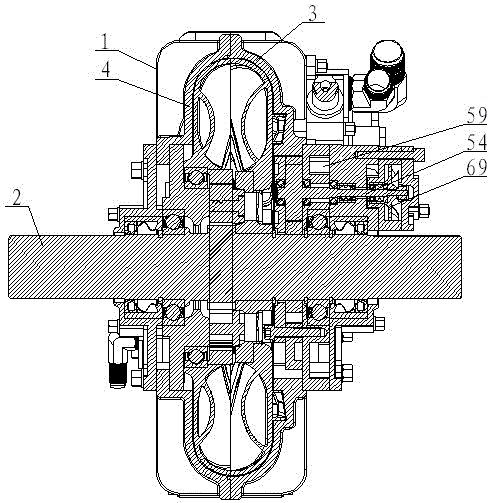
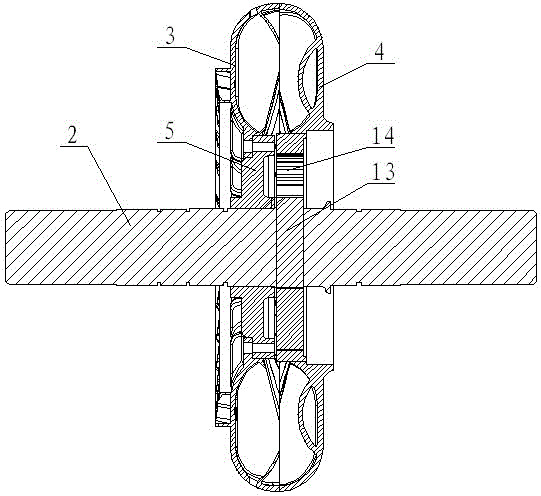
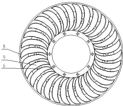
[0068] Embodiment 1: as figure 1 , 2 , 3, 4, 5, and 6, a hydraulic retarder includes a housing 1 and a transmission main shaft 2, and a front rotating impeller 3 and a rear rotating impeller 4 are arranged on the transmission main shaft 2, and on the housing 1 A brake pressure regulating switch, a gear pump and a water pump are provided, the gear pump is connected to the transmission main shaft, the water pump is connected to the gear pump, the front rotating impeller 3 is connected to the transmission main shaft 2 through the moving wheel flange 5, and the rear rotating impeller 4 It is connected with the transmission main shaft 2 through the planetary gear set, and the front rotating impeller 3 is uniformly provided with oil inlet holes 6 and oil outlet holes 7 .

[0069] Wherein, the above-mentioned front rotating impeller 3 includes a body A8, and arc-shaped blades A9 are uniformly arranged on the inner surface of the body A8, and the oil inlet hole 6 is arranged at the m...


PUM


Abstract

The invention discloses a hydrodynamic retarder. The hydrodynamic retarder comprises a case (1) and a transmission main shaft (2), a front rotating impeller (3) and a rear rotating impeller (4) are arranged on the transmission main shaft (2), a braking pressure regulating switch, a gear pump and a water pump are arranged on the case (1), the gear pump is connected with the transmission main shaft, the water pump is connected with the gear pump, the front rotating impeller (3) is connected with the transmission main shaft (2) through a driving wheel flange (5), the rear rotating impeller (4) is connected with the transmission main shaft (2) through a planetary gear set, and oil inlet holes (6) and oil outlet holes (7) are uniformly arranged on the front rotating impeller (3). The hydrodynamic retarder has the advantages that the structural design is reasonable, the braking efficiency is high, the reliability is high, simultaneously the manufacturing is simple, the manufacturing cost is low, and the service life is long.

Description

[0001] technical field [0002] The invention relates to a hydraulic retarder. Background technique [0003] In CN201896889U, a utility model patent titled "a hydraulic turbine retarder for mechanical boost regulation" is disclosed, which includes a casing, a transmission spindle, a braking structure and an oil return structure, and the casing is provided with a water cooling system. An oil reservoir, an oil inlet passage and an oil return passage are arranged on the shell; the oil outlet of the oil reservoir communicates with the oil inlet of the working chamber through the oil inlet passage, and the oil outlet of the working chamber communicates with the oil storage through the oil return passage. The oil return port of the device is connected; the oil return structure is composed of an oil inlet adjustment switch, an oil discharge switch and multiple oil return chambers; the oil inlet adjustment switch is set in the oil inlet passage, and the oil inlet adjustment switch c...

Claims


Application Information

Patent Timeline
Patent Type & Authority Applications(China)
IPC IPC(8): F16D57/02
Inventor 许金文许木华
Owner CHONGQING LINGCHUANGFU PHOTOELECTRIC TECH
Learn More