
Synchronous signal acquisition system

A technology of synchronization signal and acquisition system, applied in the field of rectifier, can solve the problem of frequency limitation of synchronization signal input signal, and achieve the effect of low performance requirements, low power consumption and simple principle

Active Publication Date: 2015-04-01
ZHUZHOU NAT ENG RES CENT OF CONVERTERS
View PDF4 Cites 0 Cited by
  • Summary
  • Abstract
  • Description
  • Claims
  • Application Information

AI Technical Summary

Problems solved by technology

[0004] In view of this, the main purpose of the present invention is to provide a synchronous signal acquisition system to solve the problem in the prior art that the acquisition of synchronous signals is limited by the frequency of the input signal

Method used


Image

  • Synchronous signal acquisition system
  • Synchronous signal acquisition system
  • Synchronous signal acquisition system

Examples


specific Embodiment

[0056] Specifically, see figure 2 As shown, a specific embodiment of the synchronous signal acquisition system of the present invention is as follows:

[0057] The isolation processing circuit 1 may include: a first resistor R1, a second resistor R2, a third resistor R3, a fourth resistor R4 and a voltage transformer PT1; the voltage transformer PT1 may be a SPT204I type voltage transformer.

[0058] One end of the parallel connection of the first resistor R1 and the second resistor R2 is connected to the first input end, and the other end of the parallel connection of the first resistor R1 and the second resistor R2 is connected to the first end of the voltage transformer PT1;

[0059] One end of the parallel connection of the third resistor R3 and the fourth resistor R4 is connected to the second input end, and the other end of the parallel connection of the third resistor R3 and the fourth resistor R4 is connected to the second end of the voltage transformer PT1 .

[0060...


PUM


Abstract

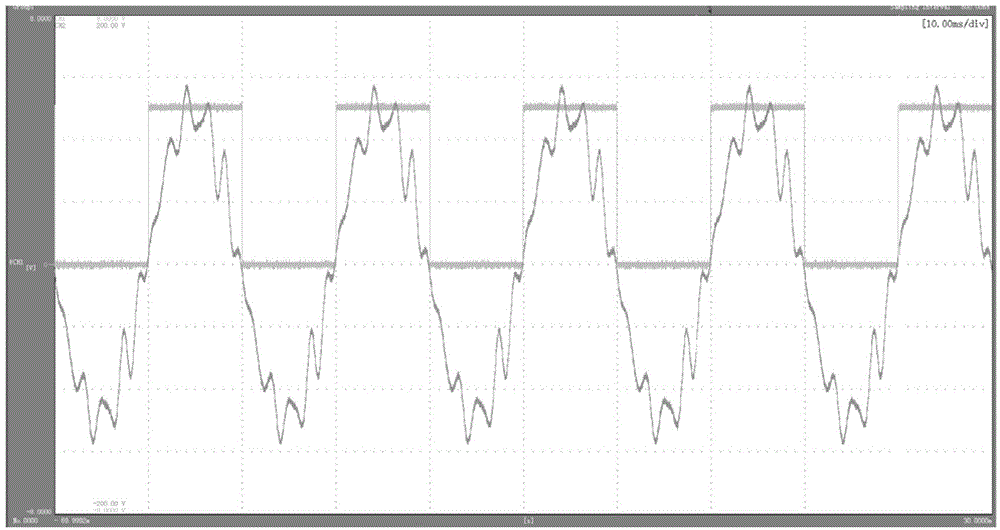
The invention discloses a synchronous signal acquisition system which is used for acquiring synchronous signals of input signals and is specifically used for acquiring synchronous signals of a variable-frequency signal system. The synchronous signal acquisition system comprises an isolation processing circuit, a filter processing circuit, a comparison circuit and a backward processing circuit which are sequentially connected with one another, wherein the isolation processing circuit is used for performing isolation voltage reduction processing on a voltage signal of a transformer secondary winding and converting the voltage signal into a current signal; the filter processing circuit is used for converting the current signal into a voltage signal similar to a square wave; the comparison circuit is used for comparing the voltage signal which is output by the filter processing circuit and is similar to the square wave and outputting a standard square wave voltage signal; and the backward processing circuit is used for performing backward processing on the standard square wave voltage signal and outputting the synchronous signal.

Description

technical field [0001] The invention relates to the technical field of rectifiers, in particular to a synchronous signal acquisition system. Background technique [0002] For conventional rectifiers and special power supply projects, it is necessary to introduce the voltage signal of the primary side of the transformer into the voltage input board of the control box as a synchronous signal for triggering. For some rectification systems with relatively small waveform distortion, sometimes the voltage signal on the secondary side of the rectification transformer is stepped down by the synchronous transformer and introduced into the system as a synchronous signal. It is extremely important for the normal operation of the entire rectifier system to ensure the accuracy of the synchronization signal phase, that is, to ensure the synchronization of the trigger pulse and the three-phase AC input. [0003] In the prior art, in a conventional rectifying power supply device, the synch...

Claims


Application Information

Patent Timeline
Patent Type & Authority Patents(China)
IPC IPC(8): H03K5/00
Inventor 初蕊曹洋谭胜武陈洁莲杨磊徐振吕顺凯王桂华蔡宇峰周绪文
Owner ZHUZHOU NAT ENG RES CENT OF CONVERTERS
Learn More