


Quick Research
Generate reliable direction feasibility study reports for your R&D in just a few steps.

Technical Q&A
Discover and master advanced knowledge NOW. Basics, ideas, possibilities, all at once.

Find Solutions
As an expert in R&D theories, this can generate solutions to your technical problems instantly.

Evaluate Feasibility
Analyze your overall solution with one click, know your potential R&D risks in advance.

Monitor Landscape
Get weekly tech updates, stay abreast of the latest tech innovations and key insights.
Flexible fixing device for optical element
A technology of optical components and fixing devices, which is applied in the direction of optical components, optics, installation, etc., can solve the problems of brittle materials, mechanical installation of quartz rods, difficult fixing, large thermal deformation, etc., and achieve accurate and stable positioning
- Summary
- Abstract
- Description
- Claims
- Application Information
AI Technical Summary
Problems solved by technology
Method used
Image

Examples
Embodiment 1
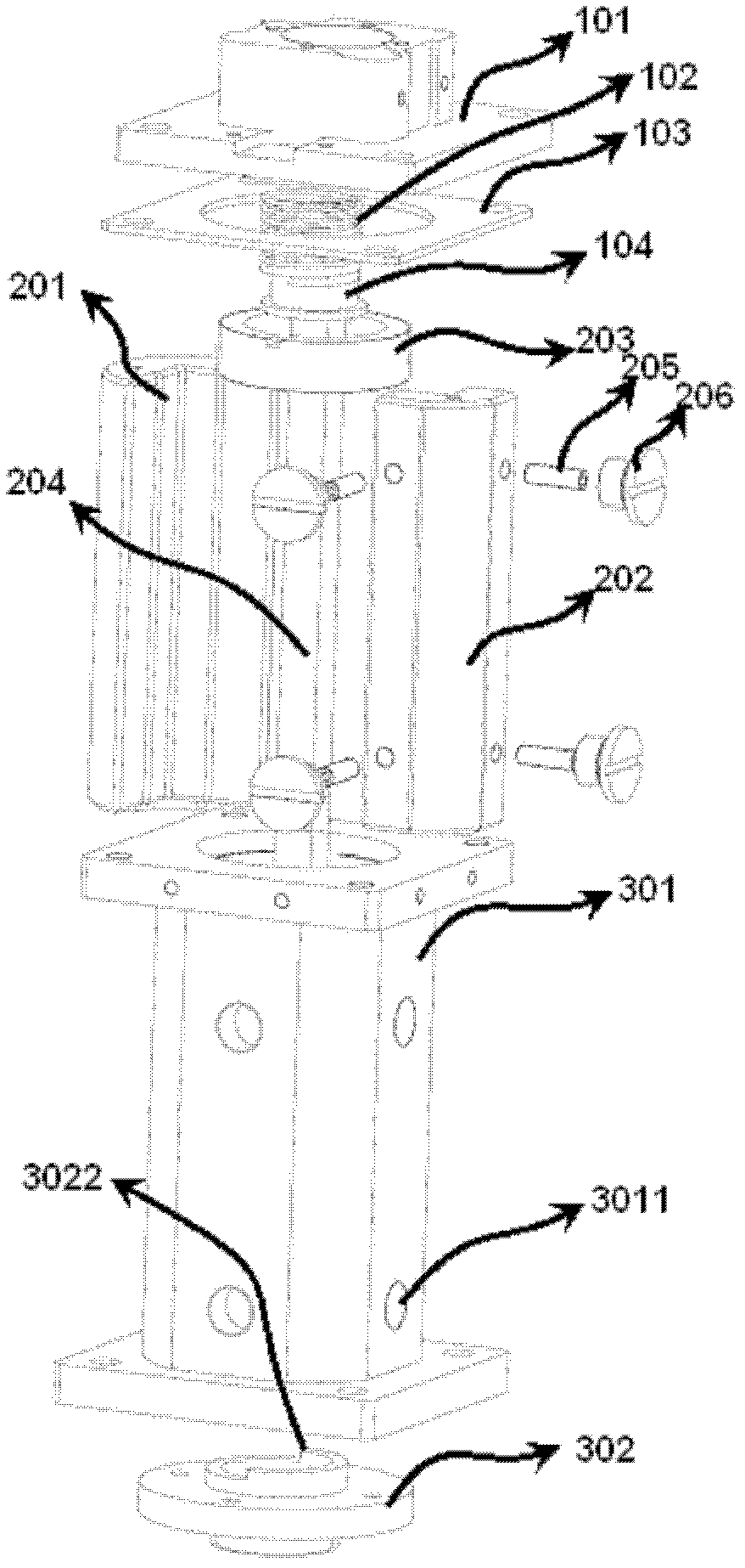
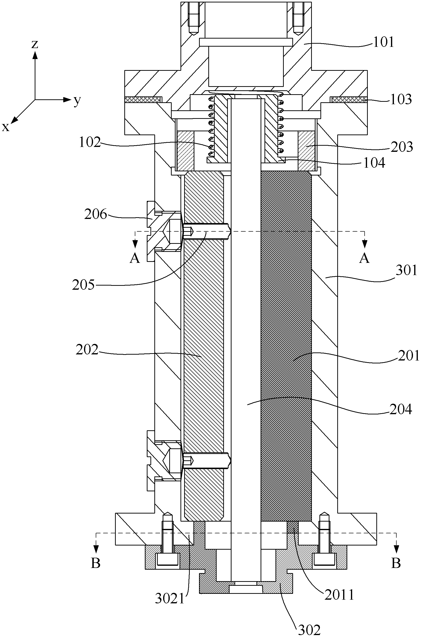
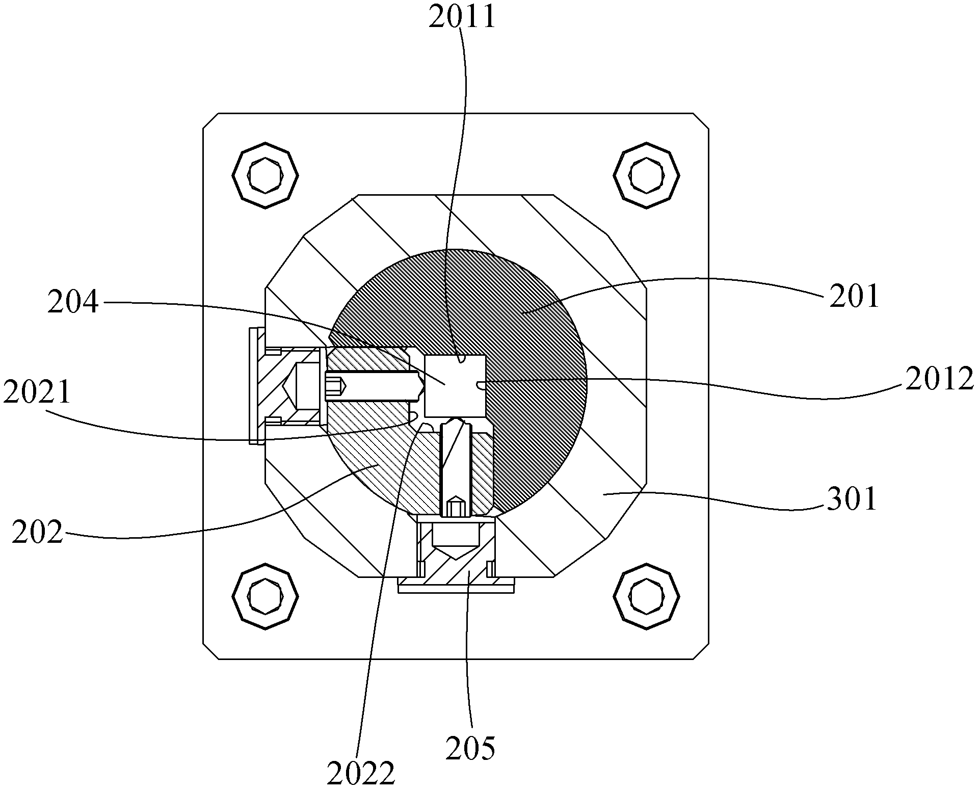
[0031] figure 1 Shown is an exploded view of the flexible fixture of the optical element of this embodiment, figure 2 Shown is the sectional view of the flexible fixing device of the optical element of this embodiment, image 3 shown as figure 2 A-A view of;
[0032] The flexible fixing device of the optical element of this embodiment is used for mechanically installing and fixing the optical element in the shape of a bar, and the axis direction of the optical element in the shape of the bar (that is, along the length direction of the optical element) is used as the Z-axis direction to establish a three-dimensional coordinate system, such as figure 2 As shown, point the right thumb to the positive direction of the Z axis, and make a fist with the other four fingers. The direction of the other four fingers making a fist is defined as the Rz direction, and the Rx and Ry directions are defined similarly;
[0033] see figure 1 , the flexible fixing device of the optical ele...
Embodiment 2
[0053] see Figure 7 The difference between the second embodiment and the first embodiment is that a thin gasket 207 is provided between the outer wall of the optical element 204 and the elastic plunger 205, and the thin gasket 207 can be made of elastic material. The thin gasket 207 is used to reduce the stress of the elastic plunger 205 on the outer wall of the optical element 204, so that the flexible fixing device of the optical element in this embodiment can meet the requirements of a certain vibration environment;
[0054] For optical elements such as quartz rods whose material is relatively brittle, the thin gasket 207 can protect the optical elements, preventing the elastic plunger 205 from exerting too much force and crushing the optical elements.
[0055] The structure of the tray 303 in the second embodiment is slightly different from the structure of the tray 302 in the first embodiment. In the second embodiment, the tray 303 is not provided with a diaphragm, but t...
PUM
 Abstract
Description
Claims
Application Information
 - R&D Engineer
- R&D Manager
- IP Professional
- Industry Leading Data Capabilities
- Powerful AI technology
- Patent DNA Extraction
Browse by: Latest US Patents, China's latest patents, Technical Efficacy Thesaurus, Application Domain, Technology Topic, Popular Technical Reports.
© 2024 PatSnap. All rights reserved.Legal|Privacy policy|Modern Slavery Act Transparency Statement|Sitemap|About US| Contact US: help@patsnap.com