Cushion ring and fluid-pressure cylinder

A technology of hydraulic cylinders and gaskets, applied in the field of hydraulic cylinders, can solve problems such as damage to U-shaped seals 26d

Active Publication Date: 2013-02-13
KYB CORP
View PDF8 Cites 0 Cited by
  • Summary
  • Abstract
  • Description
  • Claims
  • Application Information

AI Technical Summary

Problems solved by technology

[0011] If a throttle groove 21a' having a V-shaped cross-section as shown in FIG. The torrent restricted by 21a' will hit the U-seal 26d' on the rod side, which will damage the U-seal 26d'

Method used


Image

  • Cushion ring and fluid-pressure cylinder
  • Cushion ring and fluid-pressure cylinder
  • Cushion ring and fluid-pressure cylinder

Examples


Embodiment Construction

[0022] Embodiments (examples) of the present invention will be described in detail below in conjunction with the accompanying drawings.

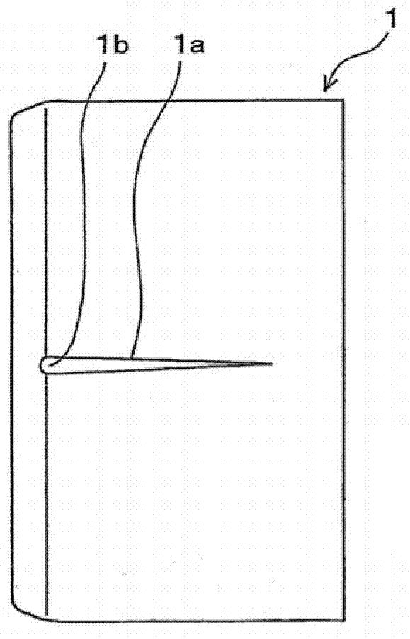
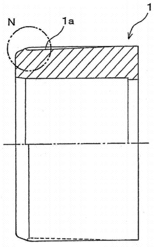
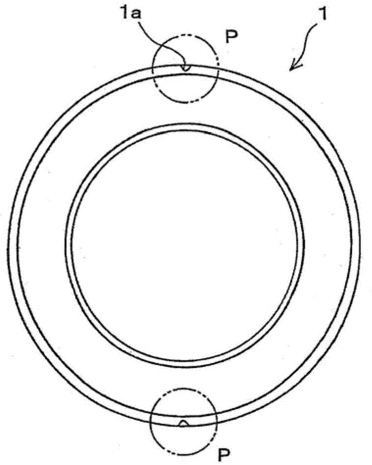
[0023] Fig. 1(a) is a top view of an embodiment of the gasket according to the present invention; Fig. 1(b) is a side view of the gasket shown in Fig. 1(a), wherein the upper part of Fig. 1(b) is Section view; Figure 1(c) is the front view of the gasket shown in Figure 1(a); Figure 1(d) is an enlarged view of N part in Figure 1(b); Figure 1(e) is Figure 1(d) ) is an enlarged view of part P in Figure 1(c).

[0024] The enlarged view of Fig. 1(e) is a transverse sectional view of the deepest portion of the throttle groove in the P section.

[0025] Fig. 2(a) is a longitudinal sectional view of an embodiment of a hydraulic cylinder using the washer shown in Fig. 1 according to the present invention; Fig. 2(b) is an enlarged view of part Q in Fig. 2(a), which shows operation and efficacy of the gasket.

[0026] The gasket 1 shown in figure 1 ...


PUM


Abstract

A cushion ring which is used between a rod-side cylinder head and a piston rod of a fluid-pressure cylinder and which is externally fitted on the piston rod to cushion a shock in the vicinity of the farthest extended end of cylinder includes a throttling groove that has a V-shaped cross section. The throttling groove extends from an appropriate position of the cushion ring to a rod-side end part and functions to throttle the flow of a working fluid flowing from a rod-side fluid chamber to an input / output port provided in a rod-side cylinder head. The throttling groove is provided at the outer periphery of the cushion ring. The throttling groove terminates at a rod-side end part with an end guide face that guides the working fluid toward a slantwise outward direction of the cushion ring.

Description

[0001] This application is a divisional application of a patent application with an application date of May 20, 2008, an application number of 200810109067.3, and an invention title of "gasket and hydraulic cylinder". technical field [0002] The present invention relates to a gasket for use between a rod-side cylinder head and a piston rod of a hydraulic cylinder, said gasket being arranged on the outside of said piston rod to cushion shocks near the furthest outstretched end of the pressure cylinder, The invention also relates to a hydraulic cylinder with such a gasket. Background technique [0003] In hydraulic cylinders using oil pressure, water pressure, etc., which supply working fluid to the bottom side of the piston and the rod side to generate linear driving force, and use gaskets to cushion the outside of the piston rod when the working fluid is supplied to the bottom side The impact that occurs when the piston is extended so that the piston contacts the cylinder h...

Claims


Application Information

Patent Timeline
Patent Type & Authority Applications(China)
IPC IPC(8): F15B15/20
CPCF15B15/222F15B15/20F15B15/22
Inventor 小林信行
Owner KYB CORP
Why Eureka
Try Eureka