
A laser-guided gmaw arc composite transverse welding method

A transverse welding, laser-guided technology, applied in laser welding equipment, welding equipment, metal processing equipment, etc., can solve the problems of undercut and weld centerline deviation, etc., to improve welding speed, reduce heat input, eliminate The effect of undercut defects

Active Publication Date: 2014-10-15
哈尔滨工大焊接科技有限公司
View PDF7 Cites 0 Cited by
  • Summary
  • Abstract
  • Description
  • Claims
  • Application Information

AI Technical Summary

Problems solved by technology

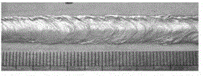
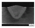
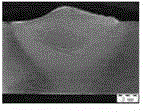
[0005] The present invention aims to solve the problems of undercut and weld centerline deviation caused by molten metal dripping down when the existing welding method is used for transverse welding in a vertical plane, and proposes a laser-guided GMAW arc compound transverse welding method

Method used


Image

  • A laser-guided gmaw arc composite transverse welding method
  • A laser-guided gmaw arc composite transverse welding method
  • A laser-guided gmaw arc composite transverse welding method

Examples


specific Embodiment approach 1

[0017] Embodiment 1: A laser-guided GMAW arc composite transverse welding method in this embodiment is carried out in the following steps:

[0018] 1. Degreasing and deoxidizing film treatment of the workpiece to be welded: first wipe the surface of the workpiece to be welded with acetone 2 to 3 times to remove oil, and then use a sodium hydroxide solution with a mass percentage concentration of 6% to 10% to treat the aluminum After soaking the alloy plate for 6 minutes to 12 minutes, rinse it with clean water, and then soak the workpiece to be welded with a nitric acid solution with a concentration of 25% to 35% by mass for 2 minutes to 4 minutes, rinse it with clean water and dry it, and then put the workpiece to be welded The surface to be welded of the part is fixed on the traveling mechanism in a horizontal manner;

[0019] 2. Filling welding wire: The diameter of the welding wire is 1.0mm~1.6mm, the dry elongation of the welding wire is controlled at 10mm~30mm, and the a...

specific Embodiment approach 2

[0025]Specific embodiment two: the difference between this embodiment and specific embodiment one is that in step one, first use acetone to wipe the surface of the workpiece to be welded twice to remove oil stains, and then use a sodium hydroxide solution with a mass percentage concentration of 8% to treat the aluminum alloy. After soaking the board for 9 minutes, rinse it with clean water, and then soak the workpiece to be welded for 3 minutes with a nitric acid solution with a concentration of 30% by mass. Other steps and parameters are the same as those in Embodiment 1.

specific Embodiment approach 3

[0026] Specific embodiment three: the difference between this embodiment and specific embodiment one or two is that the diameter of the welding wire in step two is 1.2mm~1.4mm, the dry elongation of the welding wire is controlled at 12mm~25mm, and the angle α between the welding wire and the normal line is 40 °~65°. Other steps and parameters are the same as those in Embodiment 1 or Embodiment 2.


PUM

PropertyMeasurementUnit
diameteraaaaaaaaaa
diameteraaaaaaaaaa
diameteraaaaaaaaaa

Abstract

The invention provides a laser guide GMAW (Gas Metal Arc Welding) electric arc compound transverse welding method, relates to a transverse welding method and solves the problem of the existing welding method that fused metal flows down when transverse welding is carried out in a vertical plane so as to cause undercut and deviation of a central line of a welding line. The laser guide GMAW electric arc compound transverse welding method is carried out by the following steps of: 1, carrying out oil-removing and oxidization-film-removing treatment on a work piece to be welded; 2, filling a welding wire; and 3, starting a laser device and a GMAW electric arc welding machine. With the adoption of the laser guide GMAW electric arc compound transverse welding method, the flowing of the fused metal can be controlled under the condition with a large welding current, so that the undercut defect of the welding line is eliminated and the central line of the welding line is rightly centered. The laser guide GMAW electric arc compound transverse welding method is applicable to the field of metal transverse welding engineering.

Description

technical field [0001] The present invention relates to transverse welding methods. Background technique [0002] As we all know, compared with the traditional horizontal welding, there is a big difference in the process of transverse welding. During transverse welding, the molten metal is subjected to its own gravity. When the surface tension of the molten metal is not enough to resist its own gravity, the molten metal It will flow down, resulting in defects such as undercut, weld bead and weld centerline deviation. Especially for aluminum alloy, due to its low surface tension and good fluidity, the molten metal dripping phenomenon will be more serious during the transverse welding process. [0003] At present, the research on transverse welding methods at home and abroad is mainly focused on traditional arc welding and submerged arc welding, and the control methods used are mainly pulse current control, magnetic field assisted control and rotating arc control. These meth...

Claims


Application Information

Patent Timeline
Patent Type & Authority Patents(China)
IPC IPC(8): B23K26/348B23K26/346
Inventor 雷正龙李颖陈彦宾吕涛
Owner 哈尔滨工大焊接科技有限公司
Learn More