Eureka AIR delivers breakthrough ideas for toughest innovation challenges, trusted by R&D personnel around the world.

Sheet material hydro-mechanical deep drawing forming device and method using magnetic medium to pressurize

A technology of liquid-filled deep drawing and medium, applied in the field of liquid-filled deep drawing, which can solve the problems of reduced overflow pressure in the flange area, uniformity of wrinkling deformation, etc.

Inactive Publication Date: 2013-02-13
HARBIN UNIV OF SCI & TECH
View PDF6 Cites 25 Cited by
  • Summary
  • Abstract
  • Description
  • Claims
  • Application Information

AI Technical Summary

Problems solved by technology

[0006] The present invention solves the problem of wrinkling and uniform deformation caused by the reduction of overflow pressure in the flange area (the gap between the blank holder ring and the die) when the sealing ring is not used to realize the overflow lubrication in the traditional liquid-filled deep drawing forming. In order to solve technical problems such as poor performance, and then provide a liquid-filled deep drawing device and method for sheet metal pressurized by a magnetic medium

Method used


Image

  • Sheet material hydro-mechanical deep drawing forming device and method using magnetic medium to pressurize
  • Sheet material hydro-mechanical deep drawing forming device and method using magnetic medium to pressurize
  • Sheet material hydro-mechanical deep drawing forming device and method using magnetic medium to pressurize

Examples


specific Embodiment approach 1

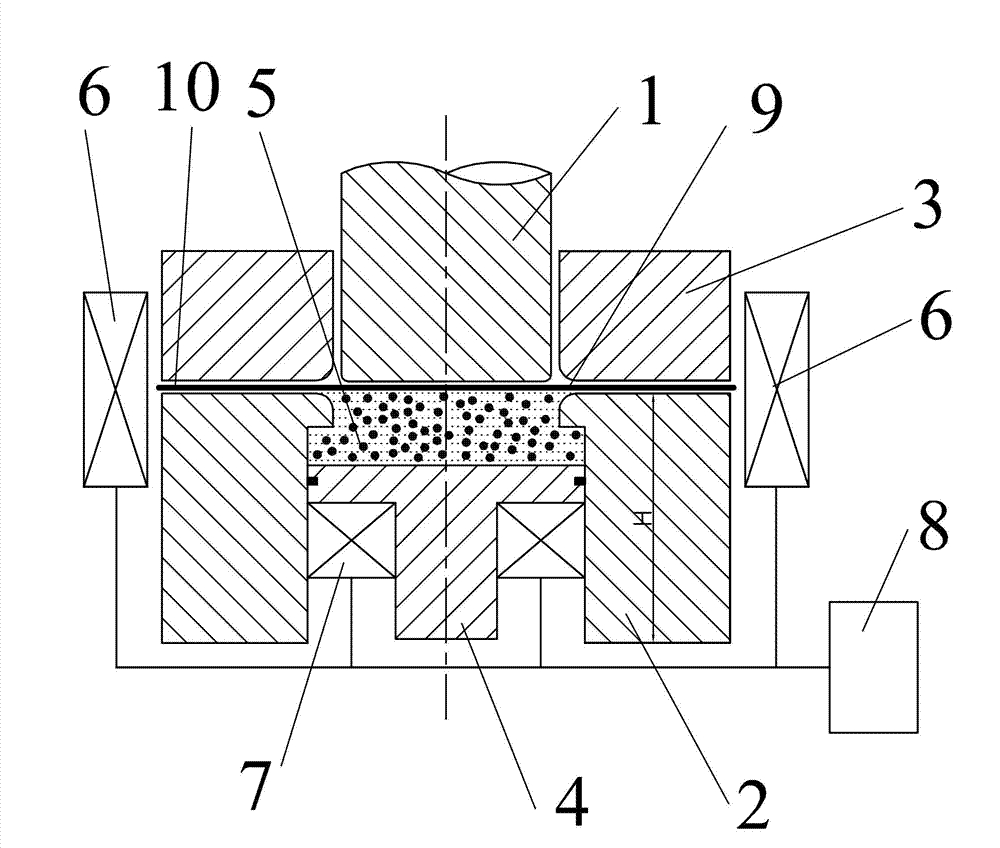
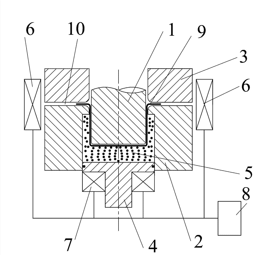
[0018] Specific implementation mode one: as Figure 1~2 As shown, the liquid-filled deep-drawing forming device for sheet materials pressurized by a magnetic medium in this embodiment includes a punch 1, a die 2, a blank holder 3, a lower plunger 4, a first coil 6, and a second coil 7 And the magnetic control unit 8; the blank holder 3 is located on the die 2, the closed liquid chamber 5 formed by the die 2 and the lower plunger 4 is used to accommodate the magnetic medium, and the punch 1 can pass through the blank holder 3 Drive the slab 9 down to enter the closed liquid chamber 5 formed by the die 2 and the lower plunger 4, the first coil 6 is arranged around the outside of the flange area 10 formed by the die 2 and the blank holder 3, The second coil 7 is arranged on the pull rod of the lower plunger 4, and the magnetic control unit 8 is used to control the magnitude of the magnetic field generated by the first coil 6 and the second coil 7, and then respectively control th...

specific Embodiment approach 2

[0019] Specific implementation mode two: as Figure 1~2 As shown, this embodiment is a sheet material liquid-filled deep drawing method using the magnetic medium pressurization of the forming device described in Embodiment 1, and the method is realized according to the following steps;

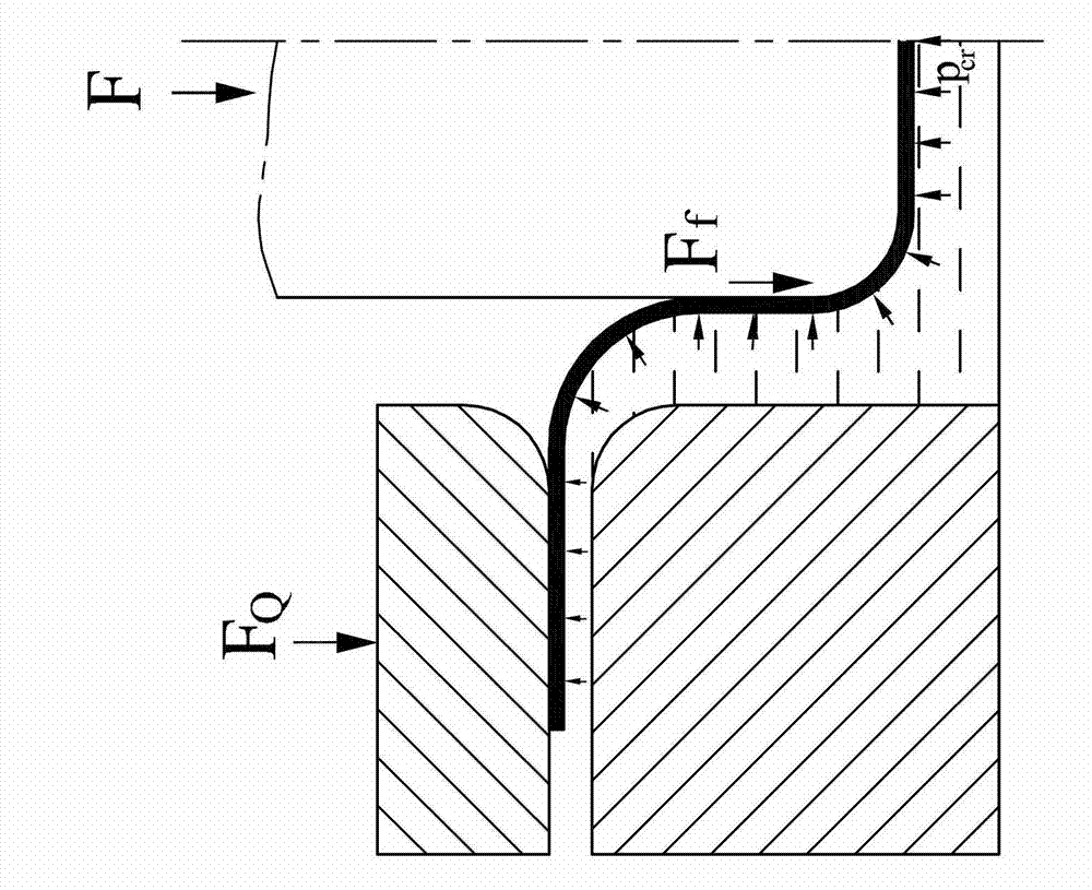
[0020] Step 1. Prepare the required magnetic medium in fluid-solid coupling state, and control its solid phase ratio to 50% to 80%; Step 2. Control the initial position of the working end face of the lower plunger 4: the working end face of the lower plunger 4 The distance from the upper end surface of the die 2 is one-third of the total depth H of the die; step 3, filling the closed liquid chamber cavity 5 formed by the die 2 and the lower plunger 4 with the above-mentioned magnetic medium; step 4. Place the slab 9 on the upper end surface of the die 2; step 5, move the blank holder 3 down to the slab 9; step 6, use the magnetic control unit 8 to control the second coil 7 at the lower plunger...

specific Embodiment approach 3

[0022] Embodiment 3: The magnetic medium in step 1 of this embodiment is composed of 7 parts of carbonyl iron powder, 2 parts of synthetic oil or ethylene glycol, and 1 part of surfactant according to the ratio of parts by mass. Other steps are the same as in the second embodiment. The viscosity degree caused by the distribution state of the magnetic medium of such components under the action of a magnetic field is more conducive to regulation. If the solid phase rate (carbonyl iron powder content) is too high, it will not be able to achieve "" "soft" back pressure; if the solid phase ratio (carbonyl iron powder) is too low, it is difficult to achieve the effect of increasing the overflow pressure at the blank holder. The magneto-inductive medium of the above-mentioned components makes the effect of "flexible" back pressure and the effect of overflow pressure at the blank holder optimal.


PUM


Abstract

The invention provides a sheet material hydro-mechanical deep drawing forming device and a sheet material hydro-mechanical deep drawing forming method using a magnetic medium to pressurize, belongs to the technical field of hydro-mechanical deep drawing, and solves the technical problems in a traditional sheet material hydraulic forming process that wrinkles are formed, the deformation uniformity is poor and the like, caused by the reason that overflowing pressure of a flange region is reduced, when a sealing ring is not used in order to realize overflowing and lubrication. A sealed hydraulic chamber formed by a concave die and a lower plunger piston is used for containing the magnetic medium; a convex die can penetrate through an edge pressing ring to drive a plate blank to move downwards to enter the sealed hydraulic chamber formed by the concave die and the lower plunger piston; a first coil is arranged on the periphery of the outer side of the flange region formed by the concave die and the edge pressing ring; a second coil is arranged on a pull rod of the lower plunger piston; and a magnetic control unit is used for controlling the sizes of magnetic fields generated by the first coil and the second coil. Firstly, a certain amount of the magnetic medium is poured into the hydraulic chamber and the edge pressing ring is moved downwards after the plate blank is placed; the viscosity and the pressure value of the magnetic mediums on a flange and in the hydraulic chamber are respectively adjusted and controlled through the magnetic fields; and a punching head is moved downwards until a plate piece is formed. The sheet material hydro-mechanical deep drawing device and the sheet material hydro-mechanical deep drawing method using the magnetic medium to pressurize are suitable for hydro-mechanical deep drawing formation of a sheet material.

Description

technical field [0001] The invention relates to a processing device and a method for increasing the drawing limit of a plate by using a magnetic medium. It belongs to the technical field of liquid-filled deep drawing. Background technique [0002] Sheet metal forming is a widely used technical method for processing and manufacturing metal hollow components. It is also an important link in the development of weapons and equipment, and it is also one of the key components to measure the development level of national military science and technology. At present, sheet metal forming technology occupies a very prominent position in the fields of aerospace, automobile, weaponry and shipbuilding. According to incomplete statistics, the amount of plate parts used in the aviation industry is more than 10,000 pieces / frame for fighter jets, over 40,000 pieces / frame for bombers, and 60,000 pieces / frame for large transport aircraft and mainline airliners, accounting for 10,000 pieces / fra...

Claims


Application Information

Patent Timeline
Patent Type & Authority Applications(China)
IPC IPC(8): B21D26/021B21D26/14
Inventor 李峰苑世剑张鑫龙隋小冲
Owner HARBIN UNIV OF SCI & TECH
Why Eureka
Eureka Blog
Learn More